There are 2 slightly different versions of the dropController. A breadboard version and a perf board version. The breadboard version has LEDs that show when the flash, camera and solenoids are active. Since the perf board version is designed to be put inside a project box it does not have the activity LEDs. Both work in the same way and use the same Arduino sketch.
Breadboard version of a 3 valve dropController

The breadboard version has LEDs, to show when the camera and the solenoids are active, and switches for draining the valves.
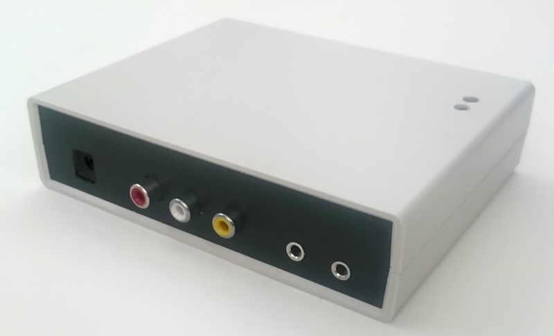
Perf Board Version of a 3 valve dropController

Since the perf board version is intended to go inside a box there no activity LEDs. I also removed the valve drain switches. Draining the valves is done through the app so no physical switches.
I now regret not keeping the valve drain switches and if I build another dropController I will include them.
Final Version of a 3 valve dropController
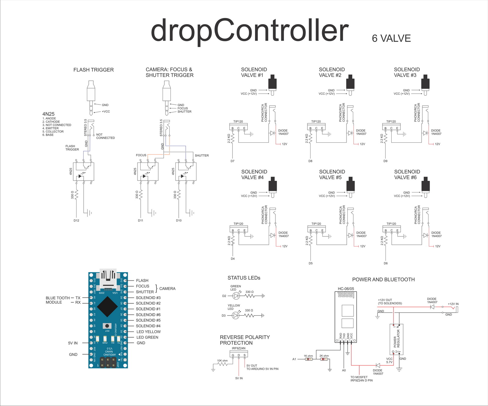
The dropController has been expanded to allow for up to 6 valves. The additional 3 valves connect to pins D4, D5, and D6 the same way as valves 1 to 3. See the circuit diagram for details.
Build Guides
Build guide for the 3 valve breadboard version.
Build guide for the 3 valve perf board version.
Please note the build guides are for a 3 valve version. As of 15.05.2016 3 additional valves can now controlled. The additional valves connect to pins D4, D5, and D6.
D4 – valve number 4.
D5 – valve number 5.
D6 – valve number 6.
Here is the circuit for a 6 valve version.
Arduino Sketch
I don’t go in to the details on how to install/upload the sketch to the Arduino. This is covered by many many other sites and a Google search will get you started. The dropController sketch is developed in IDE version 1.6.3. If you have problems with later versions revert to 1.6.3.
The sketch uses 6 separate tabs and the main sketch is on the dropControllerBT_PC tab.

In version 009 the connection type has to be set manually. To set which type of connection you are using, at about line 105 in the sketch, set the device type. The default is set for Bluetooth.
*   _____        _              _          _               _
*  / ____|      | |            | |        | |             (_)
* | (___    ___ | |  ___   ___ | |_     __| |  ___ __   __ _   ___  ___
*  \___ \  / _ \| | / _ \ / __|| __|   / _` | / _ \\ \ / /| | / __|/ _ \
*  ____) ||  __/| ||  __/| (__ | |_   | (_| ||  __/ \ V / | || (__|  __/
* |_____/  \___||_| \___| \___| \__|   \__,_| \___|  \_/  |_| \___|\___|
*
* NOTES
* The dropControllerPC app can now be used with the dropControllerBT device (as long as your PC has Bluetooth of course).
* If using  a usb connection      - set DEVICE_TYPE = 1
* If using a Bluetooth connection - set DEVICE_TYPE = 2
*/

const byte DEVICE_TYPE = 2;
If using USB connected to a computer, set DEVICE_TYPE = 1
If using Bluetooth (either with the Android app or a Windows PC), set DEVICE_TYPE = 2
In version 10 there is no need to set the device and the above has been removed.
Bluetooth Modules
Almost any Bluetooth Classic (version 2/SSP) module that supports a serial connection can be used. The ones I have are HC-06s and HC-05s on the zs-040 breakout board.
Preparing the HC-05 or HC-06 Bluetooth module
The HC-05 or HC-06 Bluetooth module should be set to 9600 baud rate. Most new Bluetooth modules are 9600 but some may not be. If using an HC-05 then it should be used in slave mode.
If you are having problems take a look at www.martyncurrey.com. I have information on setting up and using various kinds of Bluetooth modules there.
I rename the Bluetooth modules to dropController (or sometimes dropControllerBT) so they are easy to identify when connecting.
Add a Bluetooth connection status LED
If you use a HC-05 that has a STATE pin you can add a blue LED that shows when Bluetooth is connected. The STATE pin goes HIGH when a connection is made so all you need is add a blue LED plus a suitable resistor to the Bluetooth STATE pin.
If your Bluetooth module does not have a STATE pin check to see if it has a MCU-INT pin on the small Bluetooth module (you will need to check the data sheet). This is usually the same as the STATE pin on the breakout board.
Additional Bluetooth Information
HC-06 with Arduino
Arduino with HC-05 bluetooth module
Arduino with HC-05 bluetooth module – AT MODE
Android App
Before you can use the Android app you need to pair the dropController with the Android device you are using. The example below is from a Sony Z3 compact.
Bluetooth pairing the dropController
Turn on the dropController, the LED on the HC-06 should flash. The flashing means it is on but not connected.
On the Android device, turn on Bluetooth, go to the settings and select Bluetooth, then scan for devices.
Select the dropController, I have renamed the one I have to dropControllerBT, and enter the pass code. The default code for the HC-06 is 1234.
If the passcode is correct the dropController will be paired.

Start The App
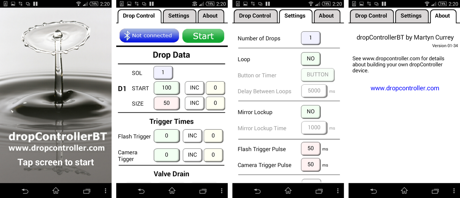
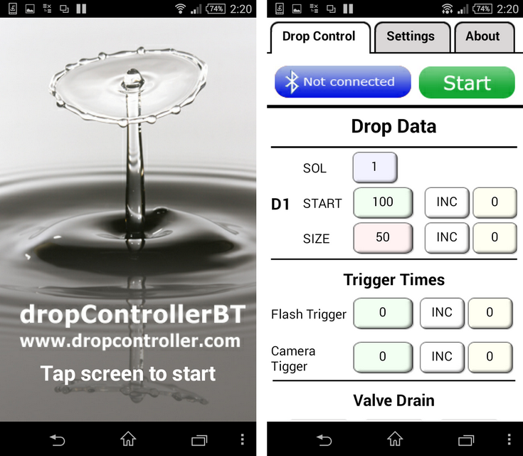
Launch the dropController app and at the start screen tap anywhere to continue to the main drop data screen.
To connect the app to the dropController device, click the Bluetooth button, this will bring up a list of the paired devices. Select the dropController from the list. Remember that the dropController has to be paired with the Android device before the app can connect to it.

After you have connected to the dropController device the Bluetooth button will change to show connected.
![]()
Clicking the Bluetooth button while connected allows you to disconnect.
Drop Data Edit Screen
This is the main screen for entering and changing the drop times.

To edit the drop data, click on the relevant drop data button.
The number of drops can be changed on the Settings screen. You can choose from 1 to 9 drops.
- SOL – the the solenoid valve number (1 to 6)
- START – the drop start time in milliseconds (0-9999). This is the time the valve opens.
- START INC – INC or DEC. Increase or decrease the start time every loop.
- START INC time – the amount of time (0-999) to increase or decrease the start time.
- SIZE – the drop size in milliseconds (0-9999). This is the amount of time the valve is open.
- SIZE INC – INC or DEC. Increase or decrease the size every loop.
- SIZE INC time – the amount of time (0-999) to increase or decrease the size.
- Flash Trigger – the flash trigger time in milliseconds (0-9999).
- Flash INC or DEC – increase or decrease the trigger time every loop.
- Flash INC time – the amount to increase or decrease the trigger time.
- Camera Trigger – the camera shutter trigger time in milliseconds (0-9999).
- Camera Trigger INC or DEC – increase or decrease the camera trigger time every loop
- Camera Trigger INC time – the amount to increase or decrease the trigger time.
When the camera shutter time is set to 0 bulb mode is activated. This will open the shutter at the start of the drop sequence and then close it after the flash has fired.
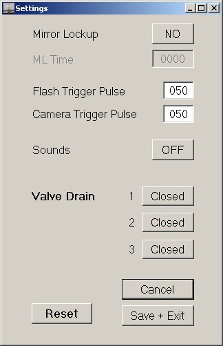
Settings Screen
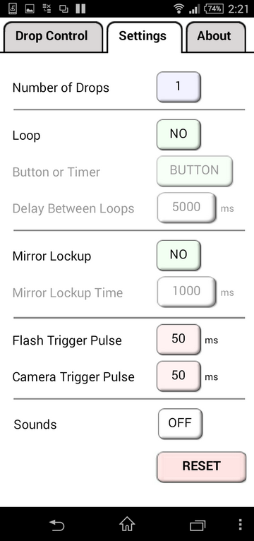
- Number of drops – from 1 to 9
- Number of valves – from 1 to 6 (not shown in the above image)
- Loop YES/NO – when YES is selected, the drop sequence will be repeated.
- Button or Timer – when in loop mode, you can select to wait for a button press or use a timer before the next sequence starts.
- Delay between loops – when using the timer, this is the time in milliseconds to wait before starting the next sequence of drops. There are 1000 milliseconds to a second. This mean 2000 = 2 seconds.
- Mirror lockup ON/OFF- Select YES if you want to use mirror lockup.
- Mirror lockup time – the time to wait after the mirror lockup command.
- Flash trigger pulse – this is the time in milliseconds the flash trigger signal will be active. 50ms is a good default value.
- Camera trigger pulse – the time in milliseconds the camera shutter trigger signal will be active. 50ms is a good default value.
- Sounds ON/OFF – turn annoying sounds on.
- RESET – reset all drop data to default values.
Mirror Lock Up
When mirror lock up is active, a pre-sequence shutter trigger will be issued. Your camera will need to be in mirror lock up mode. The mirror lock up time is the time to wait after the trigger signal. This allows time for the camera to raise the mirror and stop vibrating.
Automatically repeating / looping the drop sequence
When loop mode is active (Loop = YES) the drop sequence will automatically repeat. At the same time any INC or DEC values will be added or subtracted to the corresponding times.
Trouble shooting the Bluetooth Connection
If you are having problems getting the app to talk to the dropController you need to double check that the the Android device is connecting to the Bluetooth module and that the BT module is connected to the Arduino correctly.
When the Android device establishes a connection with the Bluetooth module the LED on the module will change. The change depends on the module you are using but on most HC-06s, for example, the LED will turn on (not flashing).
If you have a connection but still cannot get it to work the problem is likely to be the connections between the BT module and the Arduino or the baud rate. Firstly make sure the BT module is set to work at 9600 baud rate. If you are not sure about how to do this see the guides at www.martyncurrey.com.
There are 2 parts to the connection when using Bluetooth.
1. The Android device connecting to the Bluetooth module, and
2. the app connecting to the dropController/Arduino.
Connection process:
1. The Android device connects to the Bluetooth module. The LED on the BT module changes.
2. The app sends a HELLO message to the drop controller and waits for a reply.
3. The dropController gets the HELLO message and turns on the waiting LED (the yellow one)
4. The dropController sends back the HELLO message.
5. The app gets the reply and changes the BT button and the screen title to connected.
If the waiting LED on the dropController is not turning on then the dropController is not getting the HELLO message. Check the connection between the Arduino RX pin and BT TX pin.
If the LED is coming on but the BT button in the app is not changing then the app is not getting the reply. Check the connection between the Arduino TX pin and the Bluetooth modules RX pin. This is the one with the voltage divider.
Also check that the correct resistors have been used and that they are the right way around.
If you are still having problems have a look at the Bluetooth guides I have on the other website
Arduino and HC-06 (ZS-040)
Arduino With HC-05 Bluetooth Module in Slave Mode
The Windows Program
The Windows program is written in Visual Basic Net and and you will need to have the net framework installed before you can run the program. The program is 32bit (runs on 64bit) and runs on Windows XP and up. Requires .NET framework 4.0 or above. The program does not need to be installed and is run from a folder. When it first runs it will create 2 text files; one for the settings and one for the drop data.
Screen Shots
Main Screen
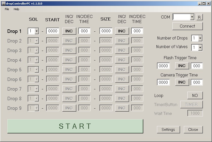
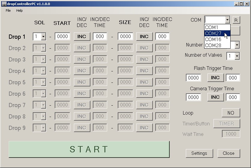 Select the COM port and click Connect. You need to know this before hand.
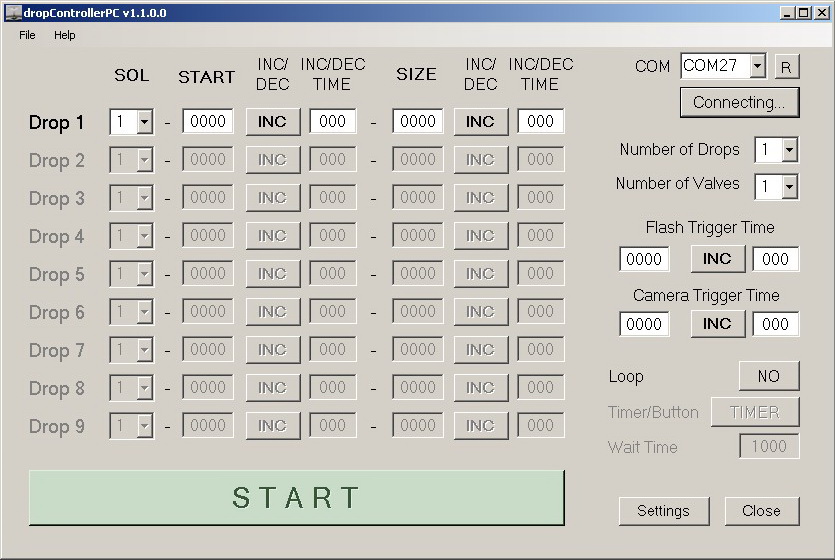 The program will attempt to connect to the dropController device
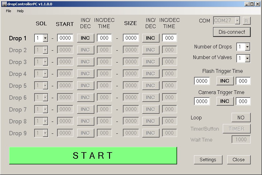 Once connected the Connect button becomes a Dis-connect button. The large START button becomes active.
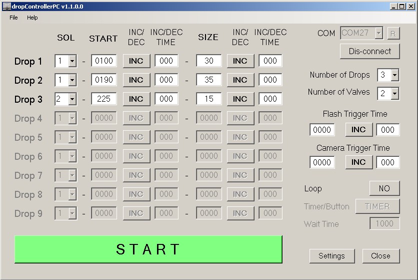 Select the desired number of drops (max 9) and the number of valves (max 6).
Settings Screen
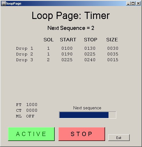
The Loop Page. The Loop Page is only active when in Loop Mode.
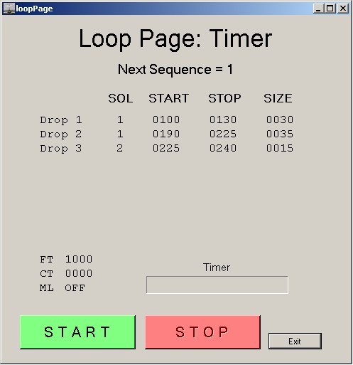 The Loop Page showing 3 drops and the timer.
 The Loop Page showing the timer waiting for the next sequence to start.
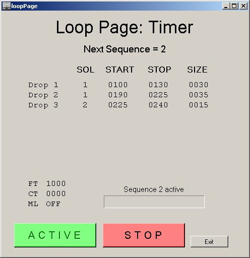 The Loop Page showing an active sequence.
For more information about the Windows app see the dropController Windows app help page
Getting Started Photographing Drops
A guide to capturing a Worthing jet is here.
An introduction to 2 drop collisions can be found here.
Comments are now closed. Please use the forum to ask questions.
Dear Martyn,
When i try to implement a_dropControl__2_01 code which has developed by you into my aurdino nano board, i get the following error ;
“Global variables use 1.612 bytes (78%) of dynamic memory, leaving 436 bytes for local variables. Maximum is 2.048 bytes.
Low memory available, stability problems may occur.”
i use the LiquidCrystal_I2C library which is recommended by you.
if you have any recomandation, or if you have any alternative working codes, i will be waiting for your help.
Thanks in advance and best ragards..
Dear Mehment,
Memory is tight for the dropController Basic but it should work fine.
what version of the Arduino IDE are you using?
Does the code compile and load OK?
I have just upgraded the Arduino IDE to version 1.6.3. The IDE now gives the amount of memory used.
When Compiling the dropControl sketch you will get a low memory warning but this is normal and does not effect the sketch.
Hi Martin! Email me please arduino sketch for dropcontrollerbt
thanx!
The sketch (and the Android app) can be downloaded from the download page.
Thanx Martin !
Hi and thank you for sharing this ! 🙂
I’m planing to build this unit and have none knowledge about programming or electronics, so this will be fun 😉 Can you tell me some about building and the valves controller and connecting this to the main controller ?
Best regards,
Erik Brede
Hi Erik,
I will post a getting started very soon.
In the meantime if you google water drop solenoid valve you will find some very useful sites.
One to start with is scantips: http://www.scantips.com/drops/shako/
Have now started to add guides. See https://www.dropcontroller.com/guides/
Hi,
The download links for the sketch and app appear to be broken
Thanks
Alan
Not sure what happened but its fixed now.
Thanks Martin….great work by the way
can I use the dropcontroller from a computer?
Not at present. I have started developing a Windows PC app in Visual Basic but I am new to VB and expect this to take some time.
the dropController is now compatible with a Windows PC either from USB or Bluetooth.
Hi Martyn, Have just finnished my first breadboard project using your code and it works like a charm 🙂 Thank you so much for sharing. My hope now is to find out how I can implement other devices in this. Have build laser, sound, shock and IR devices, and have made code to get this to work, but dont know how to put the code in to your code and expand the menu. It have been great to get som tips since I’m new to arduino and programming …
Best from Erik
It’s good to hear you have built your own controller. I have built a few devices for some friends but I believe you are the first to built your own.
The dropController actually started life as part of a camera trigger project I called camControl. I haven’t done any work on the camControl for a long time and don’t really have anything to post but look at similar devices such as the cameraxe (especially earlier versions), smartrig, AI-1 (all-in-1), and Precision High Speed Photography Trigger.
If you have the spare hardware I would suggest creating a separate device. The main reason I separated the dropController from the camControl was because it became too large and cumbersome.
I also keep a couple of Ardiono Nanos just for trying new things. For example I have a dropController simulator (a Nano and some LEDs) that I use when trying new ideas.
I tried to keep the menu function a simple as possible. In essence, all it does is copy the selected option to the menu variable and then I use a list of IF’s to determine what to do next. You may want to look at some of the Arduino menu libraries. I don’t have one to recommend but a google search should give you lots to look at.
Dear Martyn,
First of all thanks for an easy solution for water drop photography.
I am new to Arduino and so took a day to build the entire circuit and powering it on. My question is probably a basic one. In the downloads for the sketch I have multiple files and from my understanding I need to open the “dropControllerBT_006.ino” file in the Arduino software and automatically the other files open. And I need to upload the same file and the other files will be automatically compiled and uploaded to the Arduino nano. If I am wrong in understanding this please correct me.
Now after uploading the file from the software I powered up the circuit and connected the solenoid only and not the flash and camera to test if the solenoid is working. But even after running the loop from the app the solenoid didn’t work. Can you please help me with this? I have a 24v solenoid. It is working if I connect it directly to the power supply.
Please help asap as I am eager to take pictures of the lovely drop of water.
Sorry for the delay. I have just found your comments in the spam folder….
You are correct, the multiply files create a single sketch. I separated them to help keep the code organized.
How are you reducing the 24V to 5V?
Dear Martyn,
I have yet another issue. I connected my camera and after switching the camera on the camera just started taking pictures continuously with any pause. I thought if might stop but went on continuously taking pictures. And during this time the solenoid never operated. Please help me solve this issue.
I am rechecking all the connections made for any faults.
Thanks
Abhishek
If you have added the LEDs then I suggest to experiment without connecting the camera. You can use the LEDs to monitor when the camera and flash are triggered.
It sounds like you are OK with the electronics so test all the voltages coming in. 5V to the Arduino 24V to the solenoids.
What mosfet are you using?
Dear Martyn,
I figured out the issue with the solenoid not working. The Arduino nano was getting only 1.5v power from the mosfet. I don’t know why should this happen. But the camera and flash circuit is not working. I am unable to trace that yet. please help me.
Thanks
Abhishek
If you have a spare Arduino you can create a dropController simulator (an Arduino with some LEDs). This is how I test new code.
Wire up LEDs on the camera, flash and solenoid pins. Run the code and see it works. The LEDs will flash as the pins are activated.
I have managed to build the dropController bluetooth version without too much trouble but I did have some issues setting up the HC-06. Maybe you could add instructions for this. I find the control app very easy to use. Thank you for your work.
I want to know sir, if i already connected Arduino board to pc when operating the drop controller application then it is require to attach power supply of 5v is necessary, or 5v is automatically taken from usb supply
Can anybody please explain?
I want to contact anyone who made pc version successfully so i can take guidelines from him please
My email id is : divyeshghervada@yahoo.com
The Arduino will take power from an external power supply or the 5V from the USB.
When connected by USB the Arduino will use the 5V from the USB.
You can connect the Arduino to the PC without attaching an external power supply. I do this when testing and updating the software. Obviously, without the external power supply the solenoid valves will not function.
i can’t upload sketch to nano board
“Error Compiling ”
Compilation terminated
this msg shows
can you explain steps for upload sketch to board please.
sir sketch uploaded successfully but trigger not working
may be i used 4N25V instead of 4N25
A 4N25V should work the same.
I think it is more likely an issue with the solenoids. Confirm the triggers are working or not by putting LEDs (plus resistor) on D7 to D12 instead of the TIP120s and 4N25s.
thanks sir
i resolve the trigger issue but valve is not working, when i clicked “Valve Drain = Open ” from setting menu voltage measure between d7 and ground, d8 and ground, d9 and ground approx 4.61v, and valve was opened. but when close setting menu valve closed and not working .
If you have followed the circuit exactly there is a diode used for polarity protection. This causes a slight voltage drop. On all the valves I have this has not been a problem but it could be on your valves.
Sometimes the valve will stick. Check that the valve works by connecting it directly to power. Make sure you use the correct voltage. When you apply power and when you remove power the valve should click.
I’m using Arduino 1.6.6 and the sketch won’t compile.
I think the problem is with the digital IO performance library.
It says on the gitHub it is obsolete as of 1.6.0.
Any way to fix this?
Just tried with IDE 1.6.3 and 1.6.6 it compiles fine for Atmega 328P based Arduinos.
Did you place the DigialIOPerformance library in the Arduino Library folder?
What Arduino are you using?
I just commented out the include for now.
I’m using a Nano for now, but am designing a custom
board.
I will try compiling including digitalIOperformance again later.
If you are interested in my board, let me know.
Update:
Re-installed the library and everything compiles fine.
Very interested and if you want to send photos and details I can add the the website.
How can I contact you more directly?
EDIT: I have emailed you on the bell.net email address.
Dear Sir, could you tell me how i can add DigialIOPerformance library in the arduino library? im news about arduino and in the link you have posted there is only the script about library, is possible to download the file so is more easy for me? thank you
Hi Martyn
I built the Arduino part of the project and am still waiting for the BT module, so I used the PC version to test everything out. I used a relay board instead of the going with the transistor firing and it works well I figured if all the relays have the same delay then everything should equal out in the end. And it does. Great project!
A couple things I was wondering. The loop mode is not consistent, If I just tap the space bar each time I will simular drops but if I loop I get no drops. Probably a timing issue on my end.
Is there a way to have the Android version run hard wired and not use the BT I have a Mini USB OTG cable that is used for accessing external devices with the android they cost about 1.50 and I use t to control my camera with the android tablet (DSLR Controller and other apps use the same cable) BT is great but one more thing to go wrong..
Oh I tried to run it on XP but no go I am running it on W10 no problems just the odd time i would loose control and have to exit and restart the program.
Great program been looking for something like this for Months. Thanks for sharing your work and time. I will be glad to send a donation to help offset you your time..
Thanks Again
Dan C
here is a link to my FB images of the project and results
https://www.facebook.com/photo.php?fbid=10156320156545514&set=a.10156320156005514.1073741941.692540513&type=3&theater
or
https://www.facebook.com/cdvideo
Hi Dan,
re the loop/timing issue. Can you post more details. Please be aware that there is only very basic error checking on th drop times. Originally I had comprehensive checking but found it restricted things so I took it out.
I will look in to connecting the Arduino to the Android device by usb, however, I am away for the holidays and will not be back for a couple of weeks.
Nice photos on facebook by the way.
I have been trying to run the PC program on a older XP machine and I get not a valid 32 bit program and it will not run. I take it, it was compiled a a 64 bit program and will not run on a 32 bit system Can you recompile it as a 32 bit system so it can run on a 32 bit computer?
I am away for the holidays and will look in to this when I get back. It will be a couple of weeks though.
Update. I posted a 32bit version, see below. If anybody tries this please let me know if it works.
Thanks they were my first try, I used gels on the flashes..
I haven’t played with the dropper since I will get to it in a few days. I just received the BT module and will set that up for the Android. A hard wire could be used as a backup, if the BT drops out No pun intended 🙂
Have a good Holiday !
Dan C
Hi Martyn
I made a minor change to your code only because the relay board I got from Amazon is activate with a low (sink) and not a High (source) so I went in and replaced the highs to lows and lows to high.
The cost of the board with relay is only 7 dollars cheaper than putting the components together. And can be use with older high voltage flashes and has led indicators
Here is the link to the relay
http://www.amazon.com/JBtek-Channel-Module-Arduino-Raspberry/dp/B00KTEN3TM/ref=sr_1_2?ie=UTF8&qid=1451219982&sr=8-2&keywords=relay+board
Of course it is a two solenoid system with 4 relays I use manual focus, auto focus is too slow and would it focus on the background not the drop.
I crammed everything into a small 4×3 inch box, and with a transparent top you can see the relays state.
I had the BT working and I had to change the relay outputs wiring and when I turned back on the BT would not work no matter what I did ( could have been broken will try it again) went back to the PC control and changed the high lows in the code.
I tried my Windows Tablet and it works the code but does not want to communicate with the Arduino, comm issue Tablets says comm 1 but does not see it.
With windows powering the Arduino only 12 volt power is needed for the solenoids I hope when you get the Android to operate it over a wired link that the android will have enough power to operate the control and only require 12 volts for the solenoids
here is a link to the box and relay board The lose yellow is the power to the arduino disconnect as it runs over the computer connection ( I used an older 3.5 inch usb case power supply modules as it has both 5V and 12V at 2 amp for the power supply)
http://cdvideo.ca/drops1.jpg
Dan C
It does work with the Windows tablet running ver 8 windows and a OTG adaptor between the tablet and Arduino and enough power to power the board and replays
Hi, the on/off switches at solenoid valve connections are for the valve drain?
Thanks
Hi, yes they are. If you do not need then they can be omitted.
Hello
Thanks à lot for sharing your Work.
I m interesting in building à such system specially by android application control
On your website pages, I m looking for thé sketch software for thé arduino And the android application( BTcontroller) Are they available for free on your website?
May be I m wrong but I didn’t find them on the website
Thanks a lot
Kinds regards
Hello
I found the uploads now.
But when I compile the ino file, I get lots of errors relating the lib getinputperformance.
I use arduino 1.5.8
Which version do you use?
Do you have an idea about this issue?
Thanks
Hi,
you need to add the digital IO performance library. You can download from https://github.com/projectgus/digitalIOPerformance
Libraries must be installed in the correct Arduino folder before they can used.
hello
Thanks, I did a mistake when I saved this library , now the compilation works well
I m going to buy the hardware
thanks again
Michel
HI Martyn
Regarding the loop function I had the parameters set wrong and thinking it was more of a consistent loop, everything the same. I should have read your description better and realized that the inc/dec was to change the events after each drop. No need to go through the code again my Mistake
Dan c
Glad you have it working and thanks for letting me know.
Hi Martyn,
I am impressed by what you have built. Unfortunately I am not knowledgeable enough to build arduino controller by myself.
I would like to ask you whether you have thought about selling the drop controller. If you can build one for me I wish to buy it.
Regards,
Alexander
I thought about it a while ago when I was building devices for friends. The problem is it becomes expensive very quickly and doesn’t really make sense in the end. The whole point of the project was to keep costs as low as possible.
I would suggest looking at the existing systems, especially the MJKZZ and the cameraxe. Both have a strong user base for drop photography.
Dear Martyn I have build the bluetooth version and works perfect ! Great job many thanks!!. Only now i build the display version just for fun 🙂 … and i got a error see line nr 1529: numberToString( freeMemory(), 4); ->
error message:
sketch/a_dropControl__2_01.ino.cpp.o: In function `loop’:
Arduino/a_dropControl__2_01/x_Keypad.ino:1529: undefined reference to `freeMemory’
collect2: error: ld returned 1 exit status
Please advice
Kind regards lars
you need the MemoryFree library. You can get it from https://github.com/sudar/MemoryFree.
The list of required libraries has been updated.
Hi Martyn, just a question.
i tryed to compile on my arduino your software “dropController” on “Arduino sketch Version 3.01″ but I receive an error the I show below:
Arduino:1.7.4 (Windows 7), Scheda:”Arduino Nano, ATmega328”
a_dropControl__2_01.ino:160:24: fatal error: MemoryFree.h: No such file or directory compilation terminated.
Where can I get the file MemoryFree.h? Thank you in advanced. kind regards. Angelo.
Same issue as Lars. Get the MemoryFree library from https://github.com/sudar/MemoryFree.
Thank you for you replay. I have added the library that you suggest me, and now the compiler is one more step, but unfortunatly it give me more error. I use de Arduino IDE 1.7.4.
any idea? thanks.
Try IDE 1.6.3. You can download the zip/portable version that does not need to be installed.
arduino.cc/download.php?f=/arduino-1.6.3-windows.zip
I just tried the 32 bit one and it says not a valid win32 bit application.
Same as the 64 bit
I tried on a older 32 bit XP machine .
Would be nice to ave it work older 32 bit laptops can be had for a low cost and some people have them kicking around.
I now have an older 32bit xp machine. I’ll see if I can compile the app on it.
Great! I had the same “not a valid win32 bit application” error. I’m using the BT version which is working fine but the PC version would be useful…
By the way… You really made a great job, the controller works fine and the INC/DEC with LOOP function is particularly useful in this experimenting/tuning/understanding phase I am at the moment… Thank you!
What about implementing an IR photogate so to rely on the time the drop passes through it instead of relying on the time the valve opens? Do you think this would be a more reliable and repeatable event to take the time from?
Cheers
Massimo
The very first dropController used a photogate but I found it unreliable. I then I realised that since I had control over the times the valves opened and closed I didn’t actually need to use the photogate. I could just start and stop the valves when I wanted. Made life a lot easier.
I figured out what is wrong with the 32bit version of the app and why it will not run on Windows XP. The app was developed using .net 4.5 framework. XP only goes to .net 4.0….
I have now updated the 32 bit version. It has been tested on a Eee netbook runing Windows XP SP3 with .net framework V4.0.
Great! I will give it a try and let you know!
Cheers
Massimo
Yeah!!! It’s working fine on my desktop running win xp 32bit sp3 with .net framework 4.0!
Great job! Thank you!
Massimo
Good to hear and thank you for letting me know..
Martin,
Thanks for your work. Men like you help make the world a better place!!
I built a controller using you Sketch (V6) and a Nano V3. I am currently in the testing stage amnd finding that the LOOP mode does not work (stops in the “Active” mode after the first single sequence, which executes correctly). I know that you had trouble with the data parsing at one point. Do you suppose that the loop information is not being transmitted or corrupted?
Thanks!
Paul
Dear Paul,
This would indicate that the app is not receiving the “finished the sequence” (FTS) flag from the Arduino. To check this do the following.
In the sketch, set DEBUG to TRUE (this is the default value) and open the Arduino’s serial monitor.
const boolean DEBUG = true;
After the drop sequence is completed the sketch sends a single “#” character to the app. This informs the app that the sequence is finished and it can move on.
void sendFinishedDropsFlag()
{
if (DEBUG) { Serial.println(F( “FTS sent” )); }
BTserial.print(“#”);
delay(100);
}
With DEBUG set you should see “FTS sent” in the serial monitor. If you do not see the “FTS sent” message then the sketch may be freezing. If you do see the message then it means the app is not receiving the “#” character. In which case check your connection from the Arduino to the BT module’s RX pin.
Martyn,
First let me apologize for misspelling your name earlier!
Thanks for your amazingly prompt reply. Since I e-mailed you I breadboarded a second setup using a UNO board with only LEDs on the outputs and actually ran the debug test that you are suggesting. The sketch is actually communicating with the app (installed on an Samsung tablet). Here is the serial message from the sketch:
dropcontrollerBT Version 005
Ready
!
sequence = 1
D1,1,0500,0050
FT2500,050
CT0000,100
MN1000
EOD
FTS sent
STOP
The FTS message is indeed being to transmitted to the app. The STOP is probably generated by the “abort” command I issued when the app stalled after the end of the first sequence while in the in the LOOP mode (Timer mode).
The box I built, around the Arduino Nano, is actually as usable as my hardware design using CMOS chips, but the loop is too precious to give up on 🙂 !
I will probably insert additional “debug” messages in the sketch to see If I can inch toward a solution… Any suggestions are appreciated of course.
Paul
Hi Paul,
If the FTS is being sent then the issue is likely with the communication to the app. Confirm you have a working connection between the BT module and Android.
You can do this by using an Android terminal app. See http://www.martyncurrey.com/arduino-and-hc-06-zs-040/ for a basic example.
The STOP command is indeed from the in app abort button, however, the sketch no longer does anything with it…..
OOPS 🙁
Found the problem: the resistors for the 5V to 3.3V voltage were reversed so that the H6 BT Rx pin was seeing only 1.5V. The FTS flag was not being sent over the BT channel. Everything is working now. I am happy! The next step is to connect the controller to the valve fixture and start shooting collisions. Thanks again for sharing your project programs. Your documentation, both in the sketch and description is superb!
Best regards,
Paul
P.S. Who said that retirement might be boring!…
Hi Paul,
glad to hear you found the problem. Mixing up resistors is something I am very good at.
I have a 24 volt solenoid valve and a 24 volt power supply. Can this be used with your drop controller?
Yes it can, I also have some 24V Shako valves that work fine. Double check the current the your valves use first though, TIP120s can handle up to 60V and 5A maximum.
Thanks for 24 volt reply. Thats’s good news.With PC version is it possible to use only one valve to produce 2 or even 3 drops to avoid using 3 valves. How would I instruct the program screen to do this. Thanks
Yes it is possible to use one valve for multiple drops. You can create up to 9 drops using just one valve, just set SOL to 1.
Take a look at the 2 drop collision example in the Guides section (https://www.dropcontroller.com/guides/). This uses 2 drops with one valve.
When using more than one valve you can get the drops closer together, or even drops at the same time, and use different coloured liquids.
Hi Martyn
i just completed building your PC version. On the main panel I am unable to get a COM port drop down list. The COM space stays blank, The arduino power light goes on and the L light flashes. I have checked my wiring and tested continuity to connections, so they seem to be ok. Perhaps it the cheap Arduino I bought. Seems to be a cheap Chinese knockoff
Thanks
Ron
Hi Ron,
does the Arduino work OK when using the Arduino IDE?
Hi Martyn
I have obviously missed a step..I downloaded your drop Controller Version 1.0 and net framework 4,5. Do I also have to download Arduino software. Is this the digitalOperformance you refer to.I looked up an Arduino environment site which says their IDE 1.6.8 covers all Arduino boards.Sorry for my rambling. I am 80 and still have one foot firmly in analog. Afew years ago i did build a drop contrl setup whitch uses a couple of magnets passing by a reed switch controller by a pwm motor setup, a time delay trigger circuit and a 24V solenoid circuit. All this is controlled by 4 potentiometers. It actually works. I have some very good drop collision photos, but takes time to get the right combinations. I have looked on the net for a long time, and have now discovered the Holy Grail(that’s you). So finally do I need the Arduino download?
Many thanks for your time and effort
Ron
Hi Ron,
there is a sketch(program) for the Arduino called “dropControllerPC Arduino Sketch. Version R01”. It can be downloaded at the bottom of the post. The sketch needs to be compiled and then uploaded to the Arduino, this is done through the Arduino IDE. I don’t cover this as there are many guides online. A Google search for “getting started arduino” gives many many results.
“digitalOperformance” is a library or addon that is also required. You will not be able to upload the dropController sketch without adding digitalOperformance. Google “arduino add library” to see how to add.
The dropController sketch is written in version 1.6.3 of the IDE and I not sure if it works with the newer IDE. If you run in to problems with IDE 1.6.8 try the 1.6.3 version. 1.6.3 can be downloaded from https://www.arduino.cc/en/Main/OldSoftwareReleases#previous. There are 2 downloads, an install version and a non install version. The non install version runs from a folder and does not affect an installed version.
You mentioned you may have one of the Chinese clone Arduinos. If you have connections issues (unrecognized device) you may have a CH340 usb to serial chip rather than the FTDI chip. This will require a different driver which can be downloaded from the WCH website http://www.wch.cn/download/CH341SER_ZIP.html (Chinese only but the download button has English). WCH are the manufacturer.
The CH340 chip is becoming very common on clone boards, I have many, and I haven’t found any difference in use.
I was wondering if there will be an iPhone or iPad app in the future?
sorry, it is Android only. I don’t have access to idevice programming.
I just got everything running but it won’t pair with my iPhone, I think I have to get a different BT Module… I was trying to do a test app for my iPhone but I can’t connect, I was thinking to get a trigger button in the BT module to just get a shot when you press it, as an stand alone after you add the settings and configure the shot in your phone…
BT module I mean DropControllerBT
Hi Francisco,
unfortunately the dropControllerBT is Android only at this time. If you have a Windows PC you could use the PC app. Or convert to Android 😉
I am now looking at making the BT version work with a Windows PC that has Bluetooth but due to being busy at work this is likely to take a few weeks.
do you have any idea what will be a similar to IRF9Z24N Mosfet? I can’t find them in my local stores… Thank you
The FQP47P06 can be used as can any similar P channel mosfet would be suitable. Look for one that more than covers the voltage and current required and has a low RDS(on).
The IRF9Z24N has
– Drain-to-Source Breakdown Voltage of -55v
– RDS(on) of 0.175Ω
– and can handle a max of 12watts.
Martyn,
The BT based water drop controller I built according your plans and suggestions is now “in production”. I cannot thank you enough for saving me a lot of work! Compared to the discrete logic device I had designed and built, this software driven approach is like night and day. The loop mode, with the option to vary the parameters is wonderful. I have seen only a couple of collisions so far, mainly because the nozzles are not aligned properly. Each shoot is treasure hunt, and makes be feel like a kid again! Here is the link to the shots I took and processed the last two days, if you are interested. Note that these pictures are not the classic “master” collisions, but I find them pleasing just the same. It is now time to roll up the sleeves to set up various lighting scenarios…
Thanks again,
Paul
https://picasaweb.google.com/105252296412728037620/WaterDrops2016
Hi Paul,
good to hear the site has been useful and let me know when you manage to get collision working. Once you start you should find you can get them consistently.
I get as much pleasure, if not more, from playing with the dropController device and this website than I do from taking photos now.
I connect the DropControllerBT to my PC and then open the 64 Software, I can select the COM4 but when I press connect I get a message saying “Cant Connect to the DropCotroller”, any idea? should I remove the BT Module? I did Upload the “dropControllerPC Arduino Sketch. Version R01″ to my arduino… I was also wondering if I need to plug the 12V power to the board to run it without the Solenoid Valve? I’m trying to run it to test the circuit.
I’m planning to use a 12V Solenoid Valve with 10Watts specs, I bought a 2 amp DC power to be able to run it, do you think the TIP120 will support it? I can’t find an smaller valve locally.
Thanks again
thank you
There shouldn’t be any need to remove the BT module but make sure COM4 is the usb connection not the BT connection.
The PC software expects 9600 baud rate and at the moment only works over usb.
A simple test to confirm the dropControllerPC device is working.
Start the device,
open the Arduino serial monitor,
select 9600
enter “<HELLO>” (no quotes)
You should get <HELLO> back.
You can use the dropControllerBT device as long as it is running the dropControllerPC sketch.
When the PC software first connects the the dropControllerPC it opens a connection and sends a HELLO message. The Arduino then sends a HELLO back. If the PC software does not get the HELLO reply it gives the error “cannot connect” and closes the connection.
External Power Supply
If not connecting the valves then you do not need to connect the power supply. The Arduino will take power from the usb.
TIP120
Since watts = voltage * current; current = watts / voltage
This means your valves require 10w /12v amps or 0.833 amps.
TIP120s typical allow for 5amps continuous and about 8amps peak (maximum) so should be fine for your valves.
Thank you again for your help, I did get it working by re-uploading the scketch, and the COM port changed to COM5, and I was able to connect but still some times says can’t connect but eventually does connect, but it was exiting looking at the LEDs flashing when I run a test… Now I’m working on an aluminum stand for the solenoids using 80/20 aluminum extrusion …. Thank you again
Hi Martyn. Would you believe it? I bought a nano 328 FDTI version. After I did this I discovered that Windows 7 does not have any COM Ports. I think I will take up stamp collecting
Do you have the Arduino working with the Arduino IDE?
Did you install the IDE in the normal way or are you using from the non-install version?
When you install the IDE it normally installs the required drivers. If using the IDE from a folder you need to manually install the drivers.
Solving problems is a part of the fun.
Hi Martyn,
I find the technical aspect (design and building of the control devices) very stimulating and satisfying. The joy of discovering always changing results is indeed worth pursuing.
I started designing a flash controller (will be Arduino Nano based) to be able to use some of the old flashes laying around the house. These devices are automatic only, using TTL metering. The manual power level control concept is simple: the controller will sense the master flash burst and then trigger (X pin) hardwired slave units while applying a Quench signal after a user selected delay corresponding to the desired output power level. I will keep you posted on the progress…
Paul
Hi Paul,
please do and if you want to share your design and files I will happily post it.
Hi Martyn,
That’s incredible! I was actually thinking about connecting the dropcontroller PC to the computer via bluetooth and was nearly to ask you about it… And you read my mind! Actually the update came for my birthday! I take it as a present 🙂
I will definitely give it a try and let you know!
Thank you!
Cheers
Massimo
Happy Birthday
Hi Martyn,
I just notice the new version, I was working on making a PCB but only 3 valves(i guess i’ll wait to make the PCB)!!! I was wondering if you found a way to have an LED for the Bluetooth transmission and or status in the board?
I found that my HC-05 has a STATUS pin and I just added a resistor and a blue led and when I connect to the board the LED goes on, but doesn’t show activity!!
Can I ask why 3 more valves? I can’t bearly keep 1 valve going cant imaging 6 valves, hahaha… awesome job man!!! I’ll try to make it in a PCB soon,I’ll be getting the stand next week so I can start testing!!!
Thank you again.
Hi Francisco,
as you have discovered the STATE pin goes HIGH when a connection is made and I have done exactly the same as you and added a blue LED. I didn’t include this is the circuit diagrams because there are many different kinds of Bluetooth module and not all have STATE pins.
The Bluetooth modules do not have a way indicating when communication is active except by putting LEDs on the TX and RX pins (this is how the Arduino works).
I’ve been meaning to add 6 valves for a while and it was the reason I moved the pins around in an early version. The extra valves allow for things like shoot from below. This is where you have one valve pointing up and one pointing down. I should mention that I have not done much in the way of testing for 6 valves although I done quite a bit with 4 valves.
Hi, i have just finish build the dropcontroler bt and it work perfectly.
I am completly new to arduino and and very want to ad an option to the box: a push buton to do the same than on screen of the cell phone but the hardware way. I like the cycle way, but i woud like to stay the cell in my pocket or away on the table and push a boton phisicaly.
If an expert can tel me wich pin of the arduino is possible to aply it 5 volts or just short circuit it. Or do it need to ad some code to the program ?
My second wish is if it is possible to ad a simple input pin used to connect a IR detector or microphone to feed the built in delay stage to take one drop shots.
Is any interested one to help me whit this ?
P.S. I speak better in french sory
Denis Cliche
Push button start is not possible with the Bluetooth version, it is available on the original dropController device. The original version uses a key pad and LCD and is self contained.
The dropController is a dedicated water drop photography aid and does not support extra sensors such as microphones. There are many guides online to show how to do this with Arduino and it should not be too difficult to find solutions. Start by searching for the cameraxe (earlier versions) and the photodunio ( http://photoduino.com/ )
Hi Martyn,
I have built a new dropcontroller PC device, including the bluetooth module. Besides having put the wrong transistors, which I will replace with the right ones asap, I am having problems in connecting the device to the PC via bluetooth: I can manage to pair the PC to the bluetooth module, using 2 different usb dongles (Broadcom and Toshiba) but when I try to connect dropcontroller, I get the “error, cannot connect….” message. Actually something happens, the led on HC-06 turns from blinking to steady but after this the error message appears. Have you got any suggestion?
Thanx
Massimo
Make a connection using the computer then close it. This should assign a COM port to the connection. Then try connecting from the dropController.
Hi Martyn,
No success…
I tried as you said but nothing… The connection is established on COM10 (or 40 with the other dongle – led stops blinking and gets steady), then I close it (led blinking again), then try with dropcontroller on COM10 (led again stops blinking and gets steady) but dropcontroller says “ERROR! Cannot connect to the dropcontroller”. The led remains steady. If I try again with dropcontroller, I get the same message and the led remains blinking. If I try again, same message and led steady… and so on…
Don’t know what to do more…
What is your dongle? To see if I can get the same one…
Before the Toshiba and Broadcom dongles, with their own drivers, I used a no-brand-dongle with no software to install. Windows recognized it and gave two COM ports (I think IN and OUT): trying one port, I got the error message, trying the other one, dropcontroller freezed and I had to kill it using task manager…
Thanx
Cheers
I need to look into this further. I will experiment this weekend.
I may change how the Windows app opens a connection. At present it opens a new connection and then sends a HELLO message to the dropController. When the dropController replies, with another HELLO, the button changes to Connected. The “Cannot connect” error message is generated if the HELLO reply is not received within
28 seconds.I have added a connection guide using a Soleil dongle on a Windows 7 system. https://www.dropcontroller.com/connecting-dropcontrollerpc-via-bluetooth/
This will not be exactly the same for all dongles but should be close enough to get you working.
Hi Martyn,
got the bluesoleil software: it works fine with my dongle (I just tried the Broacom one), I can follow your connection guide and everything gets paired, connected and the COM is assigned… but… when I chose that COM port in dropcontroller, I get the error message and the bluetooth connection is broken; if I try again in dropcontroller, the bluetooth connection is established again, the status led on dropcontroller device turns on but error message; if I try again, the connection is broken, the led remains on but error message… and so on… The status led remains always on until I switch the power off.
Everuthing has been done on win XP SP3, so I’m gonna try on windows 7 to see if something changes… I’ll let you know…
Cheers
Massimo
Hi, see reply below.
Hi Martyn
I finally got a COM port in my windows 7. Called up your Drop Controller, which works great, with one exception. My flash does no fire. The flash LED works ok with various trigger times. To circumvernt this I used very siimple slave trigger I made some time back which uses a photodiode to trigger the flash. I attached a white diode as a photocoupler and the flash now works fine. I would ratherbe using your designed trigger, but in the meantime I am happy
Strange that the flash is not triggering.
As a test, make a small circuit using a 3V battery + LED and connect to the optocoupler on the opposite side to the dropController circuit. If the optocoupler is working the LED should flash.
See http://www.martyncurrey.com/activating-the-shutter-release/ for details.
Hi Martyn
I have solved the flash problem. I was using an old flash with terminal output of 280 volts. This worked ok with my old setup which used an SCR to trigger the flash.I discovered that tis is way too high. I rummaged through my old flash box and discovered one with 2 volt terminal voltage and it works fine.
I don’t think my solenoid valve likes Arduino as I am not getting drops the way I should. I looked up Taobao which has several “Shako” valves., but am having trouble getting into the buy now. Any hints for this?
Thanks
Ron
Taobao have just changed how their accounts work and have tightened up security for non Mainland based regions. They now want you to link to a Mainland bank account. If you do not already have an account it may be better to use ebay. ebay has many of the same sellers and although the prices are usually a little higher (but still OK) it is available in English.
You do not need to use Shakos, other types are also suitable.. The airTak is also good and, I believe, more widely available and cheaper.
Hi Massimo,
in reply to “got the bluesoleil software:”
Is it working over usb?
I used this all day yesterday on a Windows 7 system and had no problems. Once I had a connection is was very reliable.
The status LED turns on when the dropController receives a HELLO from the program. The device then replies with another HELLO. When the program gets the reply it changes the Connect button to Dis-connect. It sounds like the program is not receiving the HELLO reply. It would be worth adding some Serial.priints for debugging.
In the sketch:
At the top of the parseNewData() function (in the ParseNewData tab) add
Serial.println(receivedChars);
This will copy all received commands to the serial monitor.
void parseNewData()
{
Serial.println(receivedChars);
.
.
‘
A couple of lines down add
Serial.println(“HELLO sent”);
this will confirm the HELLO is being sent back.
// send a HELLO message back to the controller app
if (DEVICE_TYPE==1) { Serial.print(“<HELLO>”); }
if (DEVICE_TYPE==2) { BTserial.print(“<HELLO>”); Serial.println(“HELLO sent”); }
Then when you start the dropController, open the serial monitor, remember the COM port for this is the USB port not the Bluetooth one. This only works when using Bluetooth, when using the dropController over usb the hadware serial is used for communication .
The sequence for making a connection is:
Start the dropController
– dropContrfoller flashes the waiting LED to show the version number
– then waits for commands
– When it receives a “<HELLO>” command, it turns on the waiting LED and sends back “<HELLO>”
Start the program
– waits for the user to select a COM port and click the connect button.
– on click, tries opens a communication channel on the selected COM port, if successful sends “<HELLO>”
– waits for a “<HELLO>” reply.
– when it receives the “<HELLO>” reply, it changes the Connect button and turns on the START button.
If the program does not recieve a reply it will show the error message and close the connection.
If you still can’t get it working it would be worth taking a step back and confirming Bluetooth communication is actually working by using a basic sketch and terminal program. (I spent several days rewriting an Android app only to find the Bluetooth module wasn’t sending).
See http://www.martyncurrey.com/arduino-with-hc-05-bluetooth-module-in-slave-mode/ example 2. This uses a HC-05 in slave mode but works exactly the same for the HC-06. You will need to change the Bluetooth pins in the sketch to 14 and 15.
Hi Martyn,
now everything is working fine (at least with some leds connected instead of camera, flashes and valves…)
It was my fault, I put a wrong resistor in the voltage divider (10k instead of 1k)… I’m really sorry that you waste your time because of a stupid error of mine… but what you wrote really helped me to find out what was wrong: using that basic sketch and terminal program, I saw that communication was one way only, so I thought there was a bad wiring on the perfboard… and so I discovered the wrong resistor…
Now dropcontroller connects to the device in no time!
Thank you very much for your support!!
Cheers
Massimo
P.s.: there are just 3 valve drain buttons in “settings”…
Glad to hear everything is now working.
Completely forgot about the valve drain buttons…..
hello Massimo could you halp me, please answer to falduto.antonio@live.it i will happy receive help , i have a lot of problem. thank you
Hi Martyn,
A friend and I are doing this project as an engineering, independent-study, technical elective. We were wondering if it would be alright if we use material directly from this page (copied and pasted) in our report, assuming we give you credit. Once we’re done we would be happy to send you our write up.
Thank you so much for the awesome information and Arduino code!
Kyle
Hi Kyle,
this is fine and I would be very interested in seeing your project.
Thank you very much for your efforts running this site and creating drop controller. Recently I’ve built the bt version – it works perfectly! Thanks for your getailed guides, your experience and everything you shared here!!!
HI Martyn,
I’ve been able to wire up the circuit as per your guide. I’m in the testing phase now. The HC-06 Bluetooth module is working fine and I can connect the app to the board. The Solenoid valves seem to be working fine through the app also. The voltages seem to be ok. But the flash won’t trigger nor would the camera shutter release. I’ve tested the cables and those are fine. I am seeing output of around 2.8-2.85 volts on pins 4 & 5 of each of the 4N25’s (which are connected to the flash & camera jacks respectively). These voltages are at rest, I mean, when the board is powered on, but the dropController is not active. Are these values ok? Any other leads as to where I should be looking? Sorry, but I’m a complete novice to electronics.
there should not be any voltage on the pins until the flash & camera are triggered. Do you have the same make/manufacturer of optocoupler? If not the pin outs may be different. If in doubt check the data sheet.
Also check the voltage coming from the Arduino. The voltage should be zero until the flash and camera are triggered at which time they jump to 5V briefly.
I would advise not connecting a camera if there is any doubt about the wiring. For a test, use a 3V circuit made from; battery + LED + small resistor, instead of the camera and flash.
See http://www.martyncurrey.com/activating-the-shutter-release/ which is an early test I did when developing the dropController. It would be worth while trying the blink example.
Hi Martyn,
Well I figured things out. In my case it was a case of wrong assumption on pin outs on the 2.5 mm jacks for Flash & Camera. The flash fires fine now, after connecting the correct wires to the correct pin. However, the camera still doesn’t take pictures. While earlier nothing used to happen on both the flash & the camera, now the flash fires fine, and I can see that the camera screen gets activated, but I don’t see the focus happening, nor the shutter being clicked. I have a Nikon D5100 camera. Any pointers where should I be looking? The app timers got to do anything with this? Should I have the camera set on bulb mode?
Thanks for all the help.
Ajay.
Start by double checking you have the right pins for the shutter release. There is information at http://www.doc-diy.net/photo/remote_pinout/
Next, get the remote cable working manually. Connect to the camera and short the wires/pins. See if you can get the shutter to fire. Once you have the pins confirmed you can connect to the Arduino.
For now I would stay with normal shutter release and use a shutter time of halve a second or more. After you have this figured out move to bulb mode. Remember, when used this way it is the flash that takes the picture not the shutter.
Use the camera in manual focus mode. The focus connection is only there for cameras (like mine) that need focus to be active before bulb mode can be used.
Have a look at https://www.dropcontroller.com/drop-sequence/ to get an idea of what is happening when a drop is made and photographed.
hello
i install all of libraries
but i resive this message
Arduino: 1.6.7 (Windows 7), Board: “Arduino/Genuino Uno”
C:\Users\mostafa\Downloads\dropControl__V2.01\a_dropControl__2_01\x_Keypad.ino: In function ‘void loop()’:
x_Keypad:1512: error: ‘freeMemory’ was not declared in this scope
exit status 1
‘freeMemory’ was not declared in this scope
what is problem?
thank you
I cannot duplicate the problem but I am using IDE 1.6.3.
Double check you have the freeMemory library installed correctly.
Try using the I.6.3 version. You can download the zip version which does not need to be installed.
Hi Martin, I am facing the exact same problem as Ajay. I shoot with a Nikon D5200 so it might be a Nikon related issue.
I first tried to short the 3.5mm plug. This works fine when the plug is shorted properly. (Short gnd + Focus wire first then short gnd + shutter wire, with focus still shorted). This works because the shutter triggers the second I short the shutter wire.
After that I plugged in the 3.5mm plug in the device. I started a drop sequence. The camera focuses, at least it appears to because the grid in the viewfinder blinks red just like it does when the camera focuses. But after that nothing happens. However, when I short pins 4 and 5 on the focus 4N25 the shutter triggers from the signal from the arduino. So I assumed that the focus signal was not long enough. So I changed it to 999ms in the settings of the app. But this doesn’t change anything. This is where I am stuck at the moment. It feels like the focus signal is “disconnected” before the shutter releases, but I’m not sure. This is where I left of yesterday at 2AM… I tried to measure the voltage output on pin D11 of the arduino but the signal it is too fast for my multimeter. I see that it measures something, but it’s to fast for a proper readout.
Hope this makes sense to you.
Since manually shorting the connections on the jack works it sounds like a connection issue either from the arduino to the 4N25 or from the 4N25 to the jack.
A few things you can try.
1. replace the 4N25s with LEDs + resistors.
This will let you confirm the the sketch is running correctly and the pins are going HIGH as they should. The LED will flash when the focus and shutter are triggered.
2. Put the 4N25 back and replace the camera with LEDs + resistor + battery. This will allow to confirm the pin outs are correct. If connected correctly, the LEDs will flash when the focus and shutter are triggered.
3. If you cannot get either 1 or 2 to work; remove the connection between the arduino and 4N25 and using LEDs (+ resistors) instead of the camera manually trigger the 4N25. This will allow you to confirm you have the correct pin in on the 4N25.
Hi Martyn,
I already sent you an email but since Ajay faced the same problem I reckoned that it might be useful for him to share it here too.
Below my test results
“1. replace the 4N25s with LEDs + resistors.
This will let you confirm the the sketch is running correctly and the pins are going HIGH as they should. The LED will flash when the focus and shutter are triggered.”
I tried this put some LED’s in a breadboard with resistors, and it worked, both LED’s flashed.
“2. Put the 4N25 back and replace the camera with LEDs + resistor + battery. This will allow to confirm the pin outs are correct. If connected correctly, the LEDs will flash when the focus and shutter are triggered.”
With the first test succesfull I also tried this. To double check option 1, I made a combination setup of both options. In the breadboard I added the 4N25s, LED’s, resistors and a battery. Again it worked, all 4 LED’s flashed. So it appears that this is not the issue.
“3. If you cannot get either 1 or 2 to work; remove the connection between the arduino and 4N25 and using LEDs (+ resistors) instead of the camera manually trigger the 4N25. This will allow you to confirm you have the correct pin in on the 4N25.”
Just in case, I also tried this. I removed the Arduino and made a bypass from the 5Vin connection from the socket for the Arduino and connected it to the 4N25s. Once I switched the on the power source, the LED’s turned to a constant burn.
So as per my understanding all these tests confirm that the circuit works as it is supposed to. So I rechecked the shutter cable. I shorted the 3 leads, and the camera is triggered successfully. I rechecked the 3.5mm jack by replacing it with another (new) jack. I shorted the connections on the jack. The camera still triggers. I rechecked the 3.5 jack socket connector by inserting a new unused jack in the socket and connected the wires as per option 2 to the inserted jack. And again the LED’s blinked when the camera should trigger.
So it seems that the circuit is ok, the connectors for the trigger cable is connected correct, the trigger cable works. So I would think that it should work… But it still doesn’t.
I only can get it to trigger when I manually short the focus wires (pin 4 and 5 on the focus 4N25). But this way the camera keeps it’s focus locked as long as the camera is connected to the box. Disabling me to make changes in the camera settings as long as the cables stays connected. So as a final resort I could add a switch on the box that will “short” the focus wires. But I do not prefer this option.
Later this week I maybe can try it with another camera of a friend of mine, who owns a Nikon D700 but I don’t think that it will change much. But if you have any other ideas I’d be glad to hear them and I will test them.
Yours, Evert
Hi Martyn,
After a lot of thinking and some googling (I should have done it the other way around). I found that this is a common issue. The solution to this issue is to switch the leads on the connector and emitter (pin 4 and 5) of only the focus 4N25!
In the camera apparently there is a diode on the focus signal. And since the 4N25 also acts as some sort of a diode, the signal was jammed by the two diodes. By switching the focus and emitter lead on the focus 4N25 the diodes passed the signal on in the same direction. Which also explains why shorting the pins on the focus 4N25 did make it work!
This all means that I have to switch the leads on the 4N25 sockets and that I can proceed with final assembly. And start dripping! Well almost,I still want to make a rig and a Marriotte’s bottle. But I am so relieved that I finally got this part to work!
Thanks again for all your help.
Yours,
Evert.
sorry for the late reply I have been travelling.
Good to see you have solved your problem. If you don’t mind would you write up your solution with a circuit diagram so I can post on the website. Full credit will be given.
I am getting a error
Arduino: 1.6.3 (Windows 8.1), Board: “Arduino Nano, ATmega168”
^
C:\Program Files (x86)\Arduino\libraries\digitalIOPerformance/digitalIOPerformance.h:10817:123: error: stray ‘#’ in program
#error "This header's Arduino configuration heuristics have matched multiple boards. The header may be out of date."
^
C:\Program Files (x86)\Arduino\libraries\digitalIOPerformance/digitalIOPerformance.h:10821:72: error: stray ‘#’ in program
#endif
^
C:\Program Files (x86)\Arduino\libraries\digitalIOPerformance/digitalIOPerformance.h:10825:72: error: stray ‘#’ in program
#define _DIGITALIO_MATCHED_BOARD
^
C:\Program Files (x86)\Arduino\libraries\digitalIOPerformance/digitalIOPerformance.h:15743:72: error: stray ‘#’ in program
#endif
^
C:\Program Files (x86)\Arduino\libraries\digitalIOPerformance/digitalIOPerformance.h:15767:72: error: stray ‘#’ in program
#if defined(F_CPU) && (F_CPU+0) == 16000000L && defined(NUM_ANALOG_INPUTS) && (NUM_ANALOG_INPUTS+0) == 6 && defined(SIGNATURE_1) && (SIGNATURE_1+0) == 0x95 && (!defined(USB_PID) || !(USB_PID+0))
^
C:\Program Files (x86)\Arduino\libraries\digitalIOPerformance/digitalIOPerformance.h:15771:72: error: stray ‘#’ in program
#ifdef _DIGITALIO_MATCHED_BOARD
^
C:\Program Files (x86)\Arduino\libraries\digitalIOPerformance/digitalIOPerformance.h:15775:72: error: stray ‘#’ in program
#error "This header's Arduino configuration heuristics have matched multiple boards. The header may be out of date."
^
C:\Program Files (x86)\Arduino\libraries\digitalIOPerformance/digitalIOPerformance.h:15775:123: error: stray ‘#’ in program
#error "This header's Arduino configuration heuristics have matched multiple boards. The header may be out of date."
^
C:\Program Files (x86)\Arduino\libraries\digitalIOPerformance/digitalIOPerformance.h:15779:72: error: stray ‘#’ in program
#endif
^
C:\Program Files (x86)\Arduino\libraries\digitalIOPerformance/digitalIOPerformance.h:15783:72: error: stray ‘#’ in program
#define _DIGITALIO_MATCHED_BOARD
^
C:\Program Files (x86)\Arduino\libraries\digitalIOPerformance/digitalIOPerformance.h:17393:72: error: stray ‘#’ in program
#endif
^
C:\Program Files (x86)\Arduino\libraries\digitalIOPerformance/digitalIOPerformance.h:17417:72: error: stray ‘#’ in program
#if defined(F_CPU) && (F_CPU+0) == 16000000L && defined(NUM_ANALOG_INPUTS) && (NUM_ANALOG_INPUTS+0) == 8 && defined(SIGNATURE_1) && (SIGNATURE_1+0) == 0x95 && (!defined(USB_PID) || !(USB_PID+0))
^
C:\Program Files (x86)\Arduino\libraries\digitalIOPerformance/digitalIOPerformance.h:17421:72: error: stray ‘#’ in program
#ifdef _DIGITALIO_MATCHED_BOARD
^
C:\Program Files (x86)\Arduino\libraries\digitalIOPerformance/digitalIOPerformance.h:17425:72: error: stray ‘#’ in program
#error "This header's Arduino configuration heuristics have matched multiple boards. The header may be out of date."
^
C:\Program Files (x86)\Arduino\libraries\digitalIOPerformance/digitalIOPerformance.h:17425:123: error: stray ‘#’ in program
#error "This header's Arduino configuration heuristics have matched multiple boards. The header may be out of date."
^
C:\Program Files (x86)\Arduino\libraries\digitalIOPerformance/digitalIOPerformance.h:17429:72: error: stray ‘#’ in program
#endif
^
C:\Program Files (x86)\Arduino\libraries\digitalIOPerformance/digitalIOPerformance.h:17433:72: error: stray ‘#’ in program
#define _DIGITALIO_MATCHED_BOARD
^
C:\Program Files (x86)\Arduino\libraries\digitalIOPerformance/digitalIOPerformance.h:19043:72: error: stray ‘#’ in program
#endif
^
C:\Program Files (x86)\Arduino\libraries\digitalIOPerformance/digitalIOPerformance.h:19067:72: error: stray ‘#’ in program
#if defined(F_CPU) && (F_CPU+0) == 16000000L && defined(NUM_ANALOG_INPUTS) && (NUM_ANALOG_INPUTS+0) == 12 && defined(SIGNATURE_1) && (SIGNATURE_1+0) == 0x95 && defined(USB_PID) && (USB_PID+0) == 0x803C
^
C:\Program Files (x86)\Arduino\libraries\digitalIOPerformance/digitalIOPerformance.h:19071:72: error: stray ‘#’ in program
#ifdef _DIGITALIO_MATCHED_BOARD
^
C:\Program Files (x86)\Arduino\libraries\digitalIOPerformance/digitalIOPerformance.h:19075:72: error: stray ‘#’ in program
#error "This header's Arduino configuration heuristics have matched multiple boards. The header may be out of date."
^
C:\Program Files (x86)\Arduino\libraries\digitalIOPerformance/digitalIOPerformance.h:19075:123: error: stray ‘#’ in program
#error "This header's Arduino configuration heuristics have matched multiple boards. The header may be out of date."
^
C:\Program Files (x86)\Arduino\libraries\digitalIOPerformance/digitalIOPerformance.h:19079:72: error: stray ‘#’ in program
#endif
^
C:\Program Files (x86)\Arduino\libraries\digitalIOPerformance/digitalIOPerformance.h:19083:72: error: stray ‘#’ in program
#define _DIGITALIO_MATCHED_BOARD
^
C:\Program Files (x86)\Arduino\libraries\digitalIOPerformance/digitalIOPerformance.h:21345:72: error: stray ‘#’ in program
#endif
^
C:\Program Files (x86)\Arduino\libraries\digitalIOPerformance/digitalIOPerformance.h:21369:72: error: stray ‘#’ in program
#if defined(F_CPU) && (F_CPU+0) == 16000000L && defined(NUM_ANALOG_INPUTS) && (NUM_ANALOG_INPUTS+0) == 16 && defined(SIGNATURE_1) && (SIGNATURE_1+0) == 0x97 && (!defined(USB_PID) || !(USB_PID+0))
^
C:\Program Files (x86)\Arduino\libraries\digitalIOPerformance/digitalIOPerformance.h:21373:72: error: stray ‘#’ in program
#ifdef _DIGITALIO_MATCHED_BOARD
^
C:\Program Files (x86)\Arduino\libraries\digitalIOPerformance/digitalIOPerformance.h:21377:72: error: stray ‘#’ in program
#error "This header's Arduino configuration heuristics have matched multiple boards. The header may be out of date."
^
C:\Program Files (x86)\Arduino\libraries\digitalIOPerformance/digitalIOPerformance.h:21377:123: error: stray ‘#’ in program
#error "This header's Arduino configuration heuristics have matched multiple boards. The header may be out of date."
^
C:\Program Files (x86)\Arduino\libraries\digitalIOPerformance/digitalIOPerformance.h:21381:72: error: stray ‘#’ in program
#endif
^
C:\Program Files (x86)\Arduino\libraries\digitalIOPerformance/digitalIOPerformance.h:21385:72: error: stray ‘#’ in program
#define _DIGITALIO_MATCHED_BOARD
^
C:\Program Files (x86)\Arduino\libraries\digitalIOPerformance/digitalIOPerformance.h:26303:72: error: stray ‘#’ in program
#endif
^
C:\Program Files (x86)\Arduino\libraries\digitalIOPerformance/digitalIOPerformance.h:26327:72: error: stray ‘#’ in program
#if defined(F_CPU) && (F_CPU+0) == 8000000L && defined(NUM_ANALOG_INPUTS) && (NUM_ANALOG_INPUTS+0) == 12 && defined(SIGNATURE_1) && (SIGNATURE_1+0) == 0x95 && defined(USB_PID) && (USB_PID+0) == 0x9208
^
C:\Program Files (x86)\Arduino\libraries\digitalIOPerformance/digitalIOPerformance.h:26331:72: error: stray ‘#’ in program
#ifdef _DIGITALIO_MATCHED_BOARD
^
C:\Program Files (x86)\Arduino\libraries\digitalIOPerformance/digitalIOPerformance.h:26335:72: error: stray ‘#’ in program
#error "This header's Arduino configuration heuristics have matched multiple boards. The header may be out of date."
^
C:\Program Files (x86)\Arduino\libraries\digitalIOPerformance/digitalIOPerformance.h:26335:123: error: stray ‘#’ in program
#error "This header's Arduino configuration heuristics have matched multiple boards. The header may be out of date."
^
C:\Program Files (x86)\Arduino\libraries\digitalIOPerformance/digitalIOPerformance.h:26339:72: error: stray ‘#’ in program
#endif
^
C:\Program Files (x86)\Arduino\libraries\digitalIOPerformance/digitalIOPerformance.h:26343:72: error: stray ‘#’ in program
#define _DIGITALIO_MATCHED_BOARD
^
C:\Program Files (x86)\Arduino\libraries\digitalIOPerformance/digitalIOPerformance.h:28605:72: error: stray ‘#’ in program
#endif
^
C:\Program Files (x86)\Arduino\libraries\digitalIOPerformance/digitalIOPerformance.h:28629:72: error: stray ‘#’ in program
#if defined(F_CPU) && (F_CPU+0) == 16000000L && defined(NUM_ANALOG_INPUTS) && (NUM_ANALOG_INPUTS+0) == 12 && defined(SIGNATURE_1) && (SIGNATURE_1+0) == 0x95 && defined(USB_PID) && (USB_PID+0) == 0x8037
^
C:\Program Files (x86)\Arduino\libraries\digitalIOPerformance/digitalIOPerformance.h:28633:72: error: stray ‘#’ in program
#ifdef _DIGITALIO_MATCHED_BOARD
^
C:\Program Files (x86)\Arduino\libraries\digitalIOPerformance/digitalIOPerformance.h:28637:72: error: stray ‘#’ in program
#error "This header's Arduino configuration heuristics have matched multiple boards. The header may be out of date."
^
C:\Program Files (x86)\Arduino\libraries\digitalIOPerformance/digitalIOPerformance.h:28637:123: error: stray ‘#’ in program
#error "This header's Arduino configuration heuristics have matched multiple boards. The header may be out of date."
^
C:\Program Files (x86)\Arduino\libraries\digitalIOPerformance/digitalIOPerformance.h:28641:72: error: stray ‘#’ in program
#endif
^
C:\Program Files (x86)\Arduino\libraries\digitalIOPerformance/digitalIOPerformance.h:28645:72: error: stray ‘#’ in program
#define _DIGITALIO_MATCHED_BOARD
^
C:\Program Files (x86)\Arduino\libraries\digitalIOPerformance/digitalIOPerformance.h:30907:72: error: stray ‘#’ in program
#endif
^
C:\Program Files (x86)\Arduino\libraries\digitalIOPerformance/digitalIOPerformance.h:30931:72: error: stray ‘#’ in program
#if defined(F_CPU) && (F_CPU+0) == 16000000L && defined(NUM_ANALOG_INPUTS) && (NUM_ANALOG_INPUTS+0) == 12 && defined(SIGNATURE_1) && (SIGNATURE_1+0) == 0x95 && defined(USB_PID) && (USB_PID+0) == 0x8036
^
C:\Program Files (x86)\Arduino\libraries\digitalIOPerformance/digitalIOPerformance.h:30935:72: error: stray ‘#’ in program
#ifdef _DIGITALIO_MATCHED_BOARD
^
C:\Program Files (x86)\Arduino\libraries\digitalIOPerformance/digitalIOPerformance.h:30939:72: error: stray ‘#’ in program
#error "This header's Arduino configuration heuristics have matched multiple boards. The header may be out of date."
^
C:\Program Files (x86)\Arduino\libraries\digitalIOPerformance/digitalIOPerformance.h:30939:123: error: stray ‘#’ in program
#error "This header's Arduino configuration heuristics have matched multiple boards. The header may be out of date."
^
C:\Program Files (x86)\Arduino\libraries\digitalIOPerformance/digitalIOPerformance.h:30943:72: error: stray ‘#’ in program
#endif
^
C:\Program Files (x86)\Arduino\libraries\digitalIOPerformance/digitalIOPerformance.h:30947:72: error: stray ‘#’ in program
#define _DIGITALIO_MATCHED_BOARD
^
C:\Program Files (x86)\Arduino\libraries\digitalIOPerformance/digitalIOPerformance.h:33209:72: error: stray ‘#’ in program
#endif
^
C:\Program Files (x86)\Arduino\libraries\digitalIOPerformance/digitalIOPerformance.h:33213:72: error: stray ‘#’ in program
#ifndef _DIGITALIO_MATCHED_BOARD
^
C:\Program Files (x86)\Arduino\libraries\digitalIOPerformance/digitalIOPerformance.h:33217:72: error: stray ‘#’ in program
#error "This header's Arduino configuration heuristics couldn't match this board configuration. No fast I/O is available. The header may be out of date."
^
C:\Program Files (x86)\Arduino\libraries\digitalIOPerformance/digitalIOPerformance.h:33217:123: error: stray ‘#’ in program
#error "This header's Arduino configuration heuristics couldn't match this board configuration. No fast I/O is available. The header may be out of date."
^
C:\Program Files (x86)\Arduino\libraries\digitalIOPerformance/digitalIOPerformance.h:33217:169: error: stray ‘#’ in program
#error "This header's Arduino configuration heuristics couldn't match this board configuration. No fast I/O is available. The header may be out of date."
^
C:\Program Files (x86)\Arduino\libraries\digitalIOPerformance/digitalIOPerformance.h:33221:72: error: stray ‘#’ in program
#endif
^
C:\Program Files (x86)\Arduino\libraries\digitalIOPerformance/digitalIOPerformance.h:33225:72: error: stray ‘#’ in program
#undef _DIGITALIO_MATCHED_BOARD
^
C:\Program Files (x86)\Arduino\libraries\digitalIOPerformance/digitalIOPerformance.h:33234:72: error: stray ‘#’ in program
#ifndef DIGITALIO_MANUAL
^
C:\Program Files (x86)\Arduino\libraries\digitalIOPerformance/digitalIOPerformance.h:33238:72: error: stray ‘#’ in program
#define digitalWrite digitalWriteSafe
^
C:\Program Files (x86)\Arduino\libraries\digitalIOPerformance/digitalIOPerformance.h:33242:72: error: stray ‘#’ in program
#define digitalRead digitalReadSafe
^
C:\Program Files (x86)\Arduino\libraries\digitalIOPerformance/digitalIOPerformance.h:33246:72: error: stray ‘#’ in program
#define pinMode pinModeSafe
^
C:\Program Files (x86)\Arduino\libraries\digitalIOPerformance/digitalIOPerformance.h:33250:72: error: stray ‘#’ in program
#endif
^
C:\Program Files (x86)\Arduino\libraries\digitalIOPerformance/digitalIOPerformance.h:33259:72: error: stray ‘#’ in program
#endif
^
C:\Program Files (x86)\Arduino\libraries\digitalIOPerformance/digitalIOPerformance.h:33263:72: error: stray ‘#’ in program
#endif
^
C:\Program Files (x86)\Arduino\libraries\digitalIOPerformance/digitalIOPerformance.h:33273:3: error: missing terminating ‘ character
<!– –>
^
In file included from dropControllerBT_PC_009d.ino:126:0:
C:\Program Files (x86)\Arduino\libraries\digitalIOPerformance/digitalIOPerformance.h:33323:7: error: missing terminating ‘ character
You can’t perform that action at this time.
^
In file included from dropControllerBT_PC_009d.ino:126:0:
C:\Program Files (x86)\Arduino\libraries\digitalIOPerformance/digitalIOPerformance.h:5:1: error: expected unqualified-id before ‘<' token
^
In file included from dropControllerBT_PC_009d.ino:126:0:
C:\Program Files (x86)\Arduino\libraries\digitalIOPerformance/digitalIOPerformance.h:558:151: error: expected unqualified-id before ‘<' token
#include "Arduino.h"
^
C:\Program Files (x86)\Arduino\libraries\digitalIOPerformance/digitalIOPerformance.h:558:194: error: expected unqualified-id before ‘<' token
#include "Arduino.h"
^
C:\Program Files (x86)\Arduino\libraries\digitalIOPerformance/digitalIOPerformance.h:562:149: error: expected unqualified-id before ‘<' token
#include <util/atomic.h>
^
C:\Program Files (x86)\Arduino\libraries\digitalIOPerformance/digitalIOPerformance.h:562:194: error: expected unqualified-id before ‘<' token
#include <util/atomic.h>
^
C:\Program Files (x86)\Arduino\libraries\digitalIOPerformance/digitalIOPerformance.h:575:287: error: expected unqualified-id before ‘<' token
inline static void pinModeFast(uint8_t pin, uint8_t mode);
^
C:\Program Files (x86)\Arduino\libraries\digitalIOPerformance/digitalIOPerformance.h:579:293: error: expected unqualified-id before ‘<' token
inline static void digitalWriteFast(uint8_t pin, uint8_t value);
^
C:\Program Files (x86)\Arduino\libraries\digitalIOPerformance/digitalIOPerformance.h:583:249: error: expected unqualified-id before ‘<' token
inline static int digitalReadFast(uint8_t pin);
^
C:\Program Files (x86)\Arduino\libraries\digitalIOPerformance/digitalIOPerformance.h:587:248: error: expected unqualified-id before ‘<' token
inline static void noAnalogWrite(uint8_t pin);
^
C:\Program Files (x86)\Arduino\libraries\digitalIOPerformance/digitalIOPerformance.h:604:244: error: expected unqualified-id before ‘<' token
inline static bool _isPWMPin(uint8_t pin);
^
C:\Program Files (x86)\Arduino\libraries\digitalIOPerformance/digitalIOPerformance.h:608:253: error: expected unqualified-id before ‘<' token
inline static bool _directionIsAtomic(uint8_t pin);
^
C:\Program Files (x86)\Arduino\libraries\digitalIOPerformance/digitalIOPerformance.h:612:250: error: expected unqualified-id before ‘<' token
inline static bool _outputIsAtomic(uint8_t pin);
^
C:\Program Files (x86)\Arduino\libraries\digitalIOPerformance/digitalIOPerformance.h:616:249: error: expected unqualified-id before ‘<' token
inline static bool _inputIsAtomic(uint8_t pin);
^
Error compiling.
This report would have more information with
“Show verbose output during compilation”
enabled in File > Preferences.
You have selected Nano with a Atmega 168 chip. Should it be a 328 chip?
Hi, I wanna build this but I have no idea about electronics, can you explain me how and where can I start, do you write books about programming too, because I think you are soo smart that this is really science. By the way, your drops are so beautifull really. Idea, make self driving car…
Hi Martyn, I have some questions.
First,I want change board from arduino UNO to arduino MEGA,so how should I change the origin program?
Second,when I use arduino MEGA,I’ll have more pins. So if I want to add extra solenoid valves how should I change the origin program?
Thank you
Hi,
changing to the mega while keeping the code the same should be straight forward. The code should upload and compile OK.
Adding extra solenoids is possible but may prove cumbersome, not so much in adding code to control the pins but adding the menu options to allow you to enter drop times etc..
I no longer actively develop this version and all I can suggest is that you look at the code. It is heavily commented so shouldn’t be too hard to follow.
The latest dropControllerBT and PC versions allow for 6 valves. If this is sufficient maybe look at these.
Hi Martyn, I have some questions.
I change board from arduino UNO to arduino MEGA,and my android phone already connect to HC-06.
But when I use APP to control arduino MEGA,now work anymore.
What’s wrong with HC-06 and arduino MEGA?
I am busy at the moment but when I get time I will try the sketch on the mega. May take me a few days though.
In the meantime, check you have the Bluetooth module working correctly but using some basic connection sketches.
Thank you,I can connect HC-06 and arduinoMEGA.
I change RX、TX PIN to(50,51).
Now I have another problem want to ask you, in dropControllerBT you write:
// 01234567890123
// D1,1,0100,0030
// dropCommand[numDrops]-[1] is the drop number
// dropCommand[numDrops]-[2] is a ‘,’
// dropCommand[numDrops]-[3] is the valve
this means if I want to add more valves, only up to 9 valves.
Because I want to add to 16 valves, how should I change this part ?
For 16 valves you would need to change the number of digits used for the valve number. You would need to change app first though. You would also need to add the extra valves in the app. This is not something I have time to do but the AIA file for the app can be downloaded above. The app is written in App Inverter and it should be fairly straight forward to work out how it works.
Hi,
I was wondering if you could give me some feedback on my board, now with the new software that supports 6 Valves, I’m trying to work no a perf board but instead of using RCA plugs and Audio plugs I’ll use KF2510 connectors… and for power I’ll use an 8 Amp 12 V transformer…
I’ll also need to change the order for the pins flash and camera controls to make it easier to connect in the perf board, this will change the pin to function with my board right?:
const byte cam_TrigShutterPin = 12;
const byte cam_TrigFocusPin = 11;
const byte flash_TrigPin = 10;
I’m still working on placing the 2 STATUS LEDs due to all the running cables in the top… (BTW I’m an aficionado to circuits but I enjoy making projects like this)
I did a test with power but without the Arduino board just the circuit with 12 V to see if the TIP 120 works but I get power in every output and gradually gets less power in each valve output, I was wonder if you could review my circuit and if there anything I did wrong…
http://www.c1000mg.com/images/DropController03.png
the following are pictures of my progress, still waiting for some female pin sockets to put the Arduino board, lazy to go to the store I just ordered online!!
http://www.c1000mg.com/images/DropController01.jpeg
http://www.c1000mg.com/images/DropController02.jpeg
Any feedback will be greatly appreciated so I can finally start taking pictures!! 🙂
Hi,
RE Pin numbers.
Yes, changing the initial definition will change the pin.
Using 6 valves will put pressure on the power supply. A single power supply works because the valves are open only for a fraction of a second. If you are keeping the valves open for any period of time then a much bigger PSU (more amps) would be required or separate PSUs for each valve. Adding a fairly large capacity (something like 1000uF) across the power supply + and – would also help.
For testing purposes use LEDs instead of valves (you will need to use suitable resistors).
RE Circuit.
What is the purpose of the 1K resistors connected to the optocouplers? Are these for LEDs?
EDIT. I misread the circuit. I now see the resistors are connected to the valve pins and GND.
Yes the resistors is for the LEDs but they are 330 Ohms Resistors that will be connected to the red 2 pin,
for testing should I use 470 or 560 ohm resistor ?
Here is a test I did with my board and I get voltage in the solenoid pins for some reason, I cant find the reason why here is the video of my first test:
http://www.c1000mg.com/images/dropcontrollerTest1.html
you can see the controller is working fine with the software connected via USB no problems but I get a constant power in the pins for the Solenoid. The 3 and 6th solenoid have lower voltage than solenoid 1,2,4,and 5… for some reason and when the led goes on it increases the voltage a little
Help me please, my knowledge of circuits is very poor I tried to build the same controller for PC but in a perforated board… but haven’t had any luck, I believe I follow the instructions but very careful but I can’t find where I failed..
thank you
I am not sure why you would get different voltages unless there is an issue with the connections or the placement of the components.
Check:
– the resistors going in to the TIP120s (are the values correct),
– the voltage from the Arduino to the resistor. Make sure they are 5V (are the pin defined correctly),
– the 12/24 voltage going in to the TIP120s. Is this the same for all TIPs?
Dear Sir,
There is a lot of interest in your product DropController with 3 solenoid valves.
I want to buy, but is it possible? I have a Canon 5DsR.
I’m afraid not. I keep thinking about creating a kit but can never find the time to actually do it.
If you want to build your own I am more than happy to help in any way I can.
Hi Martyn. It’s really a good job, pretty nice. I would like to design and built my own one, but I’m having troubles to get a solenoid valve. I have some questions for you:
– which one did you use? Where can I buy it?
– how long is your valve open to create a single drop? Just to hava an idea about timing.
– how long is the water drop travelling from valve to the table?
– how many drops can you release in a cycle to get a multiple collision?
I think I don’t have any more questions. Any help will be welcome. Thank you very much in advance. Best regards from Spain.
– which one did you use? Where can I buy it?
for solenoid valves see https://www.dropcontroller.com/solenoid-valves/
– how long is your valve open to create a single drop? Just to hava an idea about timing.
Completely up to you. I use/have used anything from 6ms 7ms to 60ms. This is one of the things you need to experiment and play with. 6ms/7ms is the minimum to get an actual drop on some of the valves I have.
– how long is the water drop travelling from valve to the table?
Never timed it.
– how many drops can you release in a cycle to get a multiple collision?
Up to 9.
Hello, this is very interesting project, and I begin work over creation my own controller based on your. Do you have your Arduino sketch in GIT? I would like create fork for my modules.
not on GIT but you download the sketch above.
If you do not mind I would place code at GIT, with link on your site.
Do not you mind?
not at all but please add a comment saying that I no longer maintain this version of the code.
Than you!
Am loving this project. Have built the BT version using a breadboard. I have a question regarding the Arduino. Can you use an UNO? The script fails suggesting I have the libraries issue. Would I need to make any changes to the script to work with the UNO?
I no longer have an UNO to try but I suspect it is to do with the IDE rather than the type of Arduino. I also suspect the issue is with the digitalIOPerformance library which is technically out of date but still works for atmega328 based Arduinos.
Try IDE version 1.6.3. This is the one I use for developing the dropController. Later IDEs will report the library as out of date.
You can download the folder version of the IDE which does not need to be installed (it is run from the folder).
Thx. I’ll give this a go. Got a Nano on the way also to cover that base. I am now using 1.6.3 and initially installed the most up to date version, and I installed the performance files by installing from zip so hopefully they on right place. Wouldn’t be any fun if I didn’t have these little issues! Lol
Would you also kindly post a link to the folder version of IDE. I’m getting myself in a right pickle. Just when I think I’ve got it understood I fall over myself again.
https://www.arduino.cc/download_handler.php?f=/arduino-1.6.3-windows.zip
make sure you place the digitalIOPerformance library in the correct folder.
Almost embarrassed!! All problems resolved including extra ones I didn’t know about yesterday!
Ie. LED’s only go one way, UNO’s work fine but need to be disconnected to upload sketches, learn to read!! Lol. Especially the bit about re zipping the digitalperformance library files without the master extension.
Can’t wait for last bit of puzzle, the solenoid, which by all accounts are being delivered by an arthritic one winged pigeon from China!
good to hear you are solving the problems.
Martyn- thiosd is a fantastic project you have however i cant get the code to compile, i am using Ardunio 1.6.12 and the dropcontrollerBT_PC_009d, twhen verifyinh the codse i get many erros such as line 3446 error: expected constructor , destructor or type conversion before :token
sendFinishedFlag();
and
exit status 1
‘sendFinishedFlag’ was not declared in this scope
any ideas what am i doing wrong.
many thanks robin
ok restarted \arduino and rtther following error
“C:\Program Files (x86)\Arduino\tools-builder\ctags\5.8-arduino10/ctags” -u –language-force=c++ -f – –c++-kinds=svpf –fields=KSTtzns –line-directives “C:\Users\robin\AppData\Local\Temp\arduino_build_591395\preproc\ctags_target_for_gcc_minus_e.cpp”
Compiling sketch…
“C:\Program Files (x86)\Arduino\hardware\tools\avr/bin/avr-g++” -c -g -Os -Wall -std=gnu++11 -fpermissive -fno-exceptions -ffunction-sections -fdata-sections -fno-threadsafe-statics -MMD -flto -mmcu=atmega168 -DF_CPU=16000000L -DARDUINO=10612 -DARDUINO_AVR_NANO -DARDUINO_ARCH_AVR “-IC:\Program Files (x86)\Arduino\hardware\arduino\avr\cores\arduino” “-IC:\Program Files (x86)\Arduino\hardware\arduino\avr\variants\eightanaloginputs” “-IC:\Program Files (x86)\Arduino\hardware\arduino\avr\libraries\SoftwareSerial\src” “-IC:\Program Files (x86)\Arduino\libraries\digitalIOPerformance-master” “C:\Users\robin\AppData\Local\Temp\arduino_build_591395\sketch\dropControllerBT_PC_009d.ino.cpp” -o “C:\Users\robin\AppData\Local\Temp\arduino_build_591395\sketch\dropControllerBT_PC_009d.ino.cpp.o”
J:\ardionu software\dropcontrollerBT\dropControllerBT_PC_009d\dropControllerBT_PC_009d.ino: In function ‘void sendFinishedFlag()’:
J:\ardionu software\dropcontrollerBT\dropControllerBT_PC_009d\dropControllerBT_PC_009d.ino:440:8: warning: variable ‘rc’ set but not used [-Wunused-but-set-variable]
char rc;
^
Compiling libraries…
Compiling library “SoftwareSerial”
Using previously compiled file: C:\Users\robin\AppData\Local\Temp\arduino_build_591395\libraries\SoftwareSerial\SoftwareSerial.cpp.o
Compiling library “digitalIOPerformance-master”
anyway going to bed this is driving me mad but learning something new every day so cant be that bad
Just tried IDE 1.6.12 and it compiled fine.
I suspect you may have accidentally changed the sketch. Download again and see what happens.
Hello again~ I am almost finished with your project. I am down to DIY flash cable, which is on the way from amazon (cables for sony flashes are expensive and very hard to get)
I have a bluetooth connection to my samsung galaxy 5, even though in the app, the “Not connnected” bluetooth button doesn’t change to “connected”
I can press start button and my solenoid clicks and shortly after my camera takes the picture.
But the loop function doesn’t work. it sends one working round of solenoid click and camera shot, but it fails to do so for second time and beyond.
Is this a bluetooth connection error that you described earlier (my phone isn’t receiving #) or is this normal because the flash isn’t connected? Thank you in advance
And I checked all the cables & resistors(1&2kohm), even replaced them with new ones. and my app still doesn’y show “connected” button. Should i order a new bluetooth module and try again?
And also, serial communication shows that i can send messages to the arduino, but not the other way around. A1 Rx cable doesn’t seem to be working…. I should get a different 1K ohm from another store or something.
Although it could be the resistor I think it is unlikely it is damaged. More likely, you have the wrong value(s). Double check the resistor values and then double check all connections.
Follow the examples at http://www.martyncurrey.com/arduino-with-hc-05-bluetooth-module-in-slave-mode/
Found the problem. It was due to faulty jump wire or breadboard. I connected a new jump wire to a different hole in the same lane. Works like a charm. Im wating for my sony flash cable to come from the states. I live in S. Korea. Thank you very much for all the help
Comments are now closed. Please use the forum to ask questions.