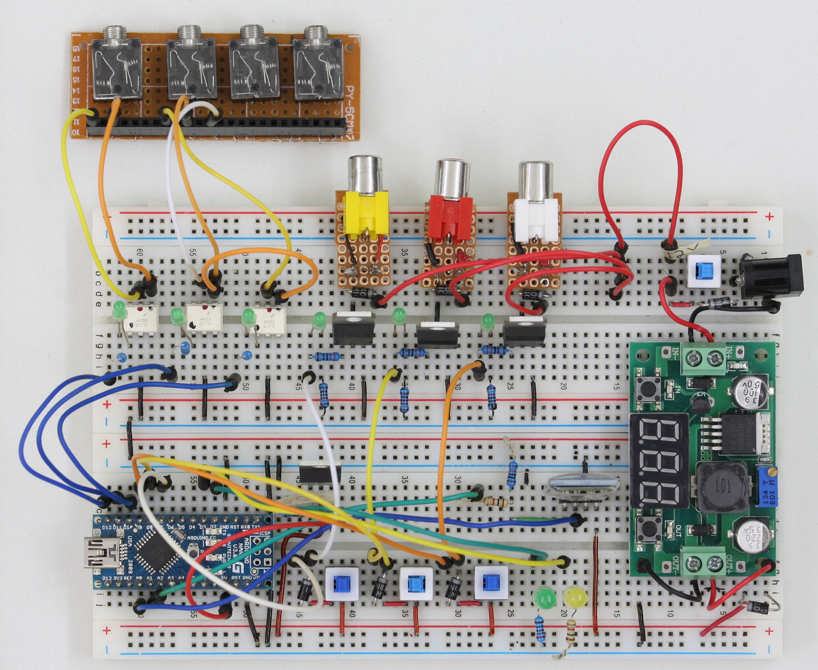
The bread board version has LEDs to show when the camera and the solenoids are active and switches for draining the valves.
Arduino Pins

Parts List: Bread Board Version
Bread Board x 2
Various wires
Arduino Nano x 1 (or any type of AVR based Arduino)
HC-06 Blue Tooth module x1 (HC-05 can also be used)
DC-DC step down power supply x 1 (can also use a LM7806 based circuit)
LEDs x 8 (9 if you want to add one to the power in)
– 3 x LED for camera trigger activity
– 3 x LED for solenoid valve activity
– 1 x Green LED for status – waiting
– 1 x Yellow LED for status – active
On/off switches x 4
– 1 x main power on/off switch
– 3 x solenoid valve drain
3.5 stereo sockets x 2
RCA/Phono sockets x 3
Power socket x 1
4N25 optocoupler x 3 (Anything similar also suitable)
TIP120 x 3
F9Z24N mosfet x 1 (or similar)
330 ohm resistor x 5
1K ohm resistor x 4
2K ohm resistor x 1
2.2K ohm resistor x 3
10k ohm resistor x 1
1N4007 diode x 8
3.5mm jacks to connect to the camera and shutter leads
RCA/Phono jacks to connect to the solenoid valves.
Of course, you will also need solenoid valves, a power supply and an Android device.
Circuit Diagrams

Camera and flash triggers
The camera trigger circuit uses 4N25 opto-couplers as digital switches. Opto-couplers allow the Arduino to trigger the camera and flashes without having a direct electrical connection. The camera focus and camera shutter triggers use separate opto-couplers which then go to the same 3.5 connector. I have a Canon camera which requires both focus and shutter to be active for bulb mode to work.
Close up showing the opto-couplers

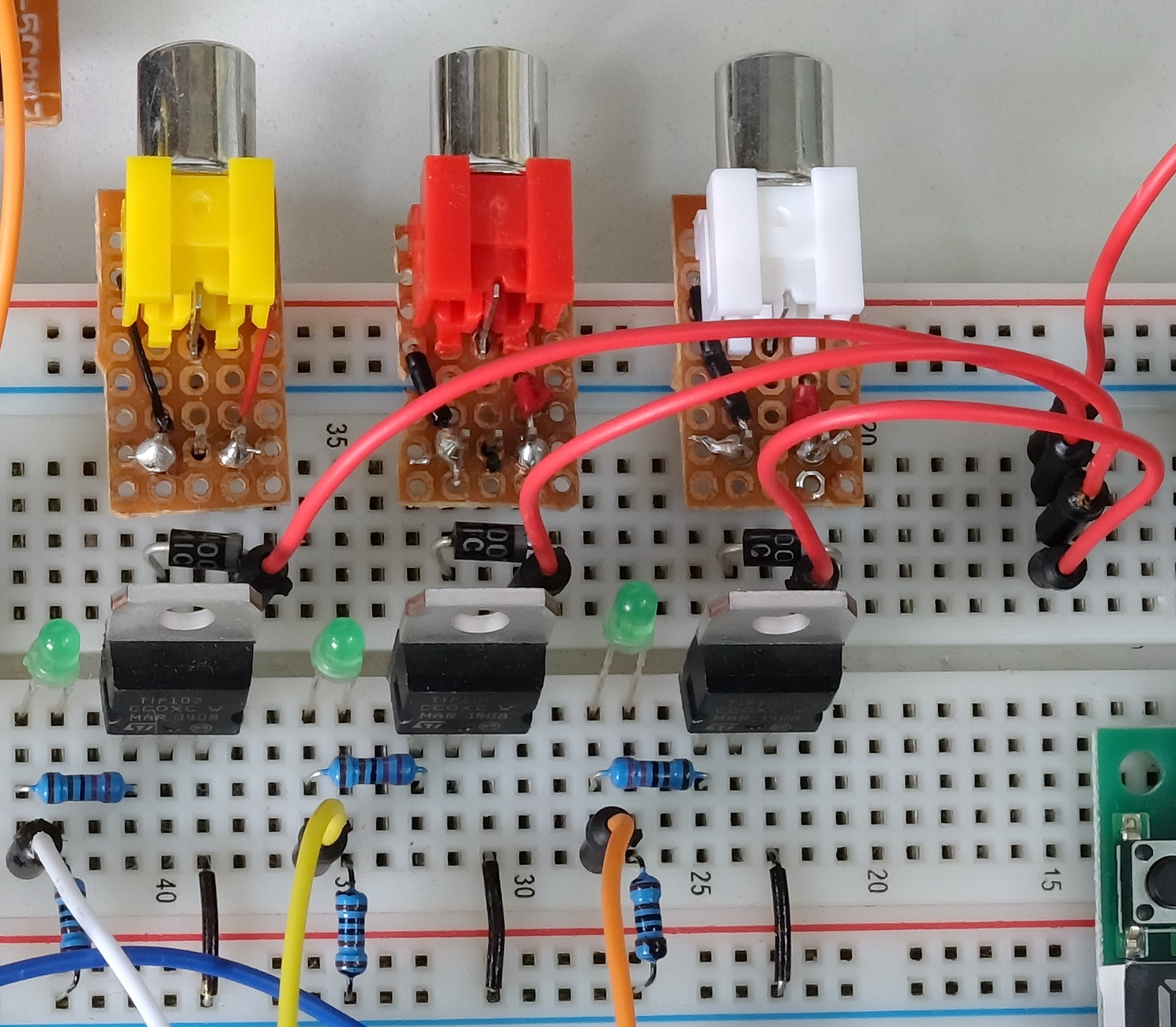
Solenoid valve connections
The solenoid valves are controlled through TIP120’s. These are used as digital switches similar to the opto-couplers. The difference is the TIP120’s allow a larger voltage/current to be switched.
Close up showing the solenoid valve connectors.
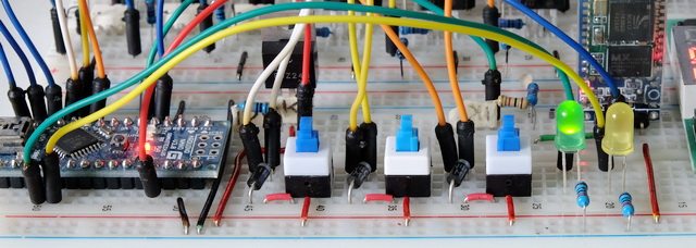
Status LEDs
I previously used an LCD to show the device status and I suddenly realised I didn’t need this. I could show the same information using a couple of LEDs. A green LED shows when the dropControllerBT is waiting. A yellow LED shows when the device is active.
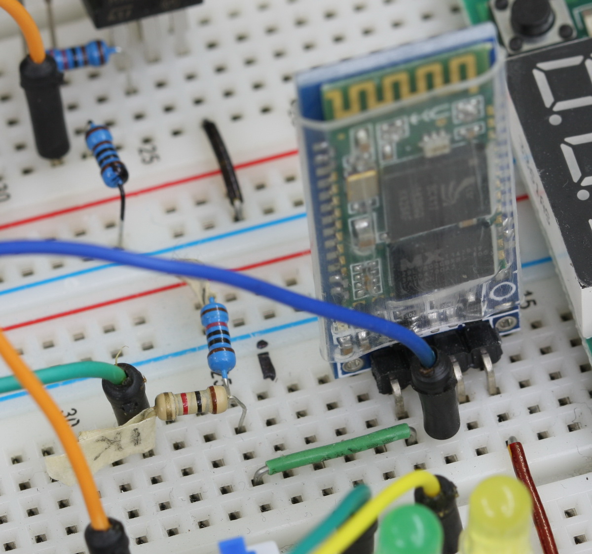
HC-06 Bluetooth Module
The HC-06 bluetooth module has power regulators to allow an input voltage from 3.6v to 6v. The module is actually a 3.3v device and only the voltage in pin can use a voltage larger than 3.3v. The RX and TX (receive and transmit) pins are still 3.3v. The Arduino will see a 3.3v as HIGH and so the TX pin of the BT module can connect directly to the RX pin on the Arduino (pin D2). This is not the same for the RX pin on the BT module. The RX pin is 3.3v in and we need to reduce the Arduino’s 5V to 3.3v by using a voltage divider. A simply voltage divider is 2 resistors in series. To convert 5V to 3.3v I use 1 x 1K and 1 x 2K resistor.
Note: A HC-05 in slave mode can be used instead of the HC-06.
As a quick guide to the voltage divider; 1K + 2K = 3K. 1K is a third of 3K so it reduces the voltage by a third.
One third of 5V is 1.66 and 5-1.66 = 3.33 which is what we want. Putting the resistors the other way would reduce the voltage by 2 thirds. For more information on voltage dividers have a look at the Sparkfun tutorial
Double check the resistors you are using. It is very easy to use the wrong values.
Power
The dropControllerBT device and the solenoid valves are powered from a single 12V wall wart power supply. The 12V power in goes to the solenoid valve connectors (through a diode) and also to a DC-DC step down converter. The converter reduces the voltage in to 5.7V. This goes to a 1N4007 which reduces the voltage to 5.0V and then connects to the Arduino 5V pin and the bluetooth module.
I am currently using a converter with a display to drop the 12V to 6V. When I eventually get round to putting this project in a case I will use a smaller converter with no display.

Reverse Polarity
In an earlier version of the dropCopntroller, I had a weird problem, when the Arduino was connected to a computer by usb and at the same time the device was powered by the external power supply, the computer would crash when the usb cable was unplugged. I fixed this by adding a diode to the 5V out line on the Arduino. This stopped the computer crashing but unfortunately the diode ate too much power (fairly high forward voltage drop). I later swapped out the diode for a mosfet. The mosfet offers the same polarity protection as the diode but without the large forward voltage drop.
When there is power on the 5V line the mosfet is turned on and allows current to flow. Remove the 5V and the mosfet turns off.

Hi,
thank you for this marvellous project.
I have only a question. As I’m newbie in electrical project and I wouldn’t like to risk my DSLR with connectors, I would like to build only the part related to solenoid valves (I have already a laser trigger to shoot).
Would the Controller work also without camera connection? And would the app work too?
Thanks a lot for your help
Hi,
yes, all parts work even if a camera or flash is not connected
You can build the complete device and simply not connect a camera or just leave out the camera connection part of the circuit
Marvellous!
Thank you very much!
Flavio
Hi. Loving this project. I have a question regarding the components. When I have looked, they seem to come with various wattages and ohm values. Which do I get? Eg. F9Z24N Comes as 0.175 ohm or 175 mohm. ?? Resistors as 2W 330ohm, 0.6W 330ohm, 3W 330ohm etc.
I’m novice with electronics so trying to follow baby step by baby step if you get my meaning. Cheers.
There is only one F9Z24N and the 0.175 ohm and the 175 mohm are values for different aspects of the chip.
Resistors come is various wattages; most hobby electronics use 1/4 watt or 1/2 watt and for the drop controller either of these are suitable.
With resistors you can use a larger wattage, for example, use a 1/2 watt instead of a 1/4 watt but it is not recommended to use a lower wattage.
Thank you. Purchases all under way. Deliveries awaited. Sleepless nights ahead, but looking forwards to it.
Should have posted these above.
Take a look at the following. They help determine what wattage resistor to use in a circuit.
http://www.instructables.com/id/Electronics-for-Absolute-Beginners-Chapter-2/step7/Determine-Needed-Wattage-for-Resistor/
https://www.robogaia.com/how-to-calculate-resistor-wattage.html
I’m very new to arduino and your project is the only reason iam currently studying it. Thank you in advance~
I am wondering why the power socket and IN(-) at power regulator(DC-DC step down converter) is not connected to GND in your breadboard.
They are but it might not be easy to see.
I use the GND wire from the DC converter to hold the DC converter in place. The GND wire from the convertor goes through the hole and in to the breadboard. I then connect the same column of the breadboard to the GND rail using a second wire.
I am very sorry to bother you but i was talking about the wires between DC converter and the power socket. In the circuit diagram, Ground output from the power socket goes to IN(-) and this in turn goes to GND at arduino board.
I cant find a GND wire that connects
1. GND from power socket and
2. IN(-) from DC converter
in your photos, even though it’s evident in the circuit diagram.
Thank you
The GND is common all the way through the circuit. This means the GND at both sides of the DC converter is the same. If you follow the GND wires you should find they all join up somewhere.
I tried to make this as clear as possible by using black for the GND wires but due to the angle of the photos it may not be completely easy to follow.
Whenever you have a photo of a circuit that is not clear always refer to the circuit diagram. Don’t just rely on the photo.
What a fantastic design. I’ve been using a raspberry pi and some custome python code I wrote for my water drops and I’ve been looking for a better controller or at least better software. This is a fantastic design. It took only a few minutes to have the whole thing up and running on a breadboard with a pro mini and it’s awesome. I thank you for your wonderful work.