Introduction
dropControllerV3 is a mature, well tested water drop device. dC3 started life as a DIY only project, became a finished product and went back to being DIY only. dropControllerV3 is now the official dropController DIY option.
While dropControllerV4 may appear to surpass version 3, version 3 works in a similar way and shares many of the same functions as the newer V4. dC3 is very capable, powerful, and fully supported.
The main difference between V3 and V4 is compatibility. V3 is compatible with Windows OS and Android* devices only, dropControllerV4 is compatible with any device/OS that has a web browser, such as Windows, IOS/apple, Linux, Android.
*Google may remove the option of side loading Android apps. If this happens dropControllerV3 will become Windows PC only. For now, it’s a case of wait and see.

Circuit
The dropControllerV3 circuit is fairly straight forward and building one should not be that difficult for anybody with any kind of electronics or Arduino experience. It will be little harder, but not impossible, if you are totally new to electronics.
dropControllerV3 has been designed to make construction straight forward using commonly available components.
I tried to keep the circuit as simple as possible and have tried to use commonly available parts. For example 4N35s and IRL540N/IRLZ44N mosfets. The same style 3.5mm stereo socket is used for the camera, flash, and AUX trigger connections even though the flash and AUX connections are single channel. The only socket that needs to be stereo is the camera trigger connector. I use PJ307 3.5mm sockets simple because they are breadboard friendly and just kept using them.
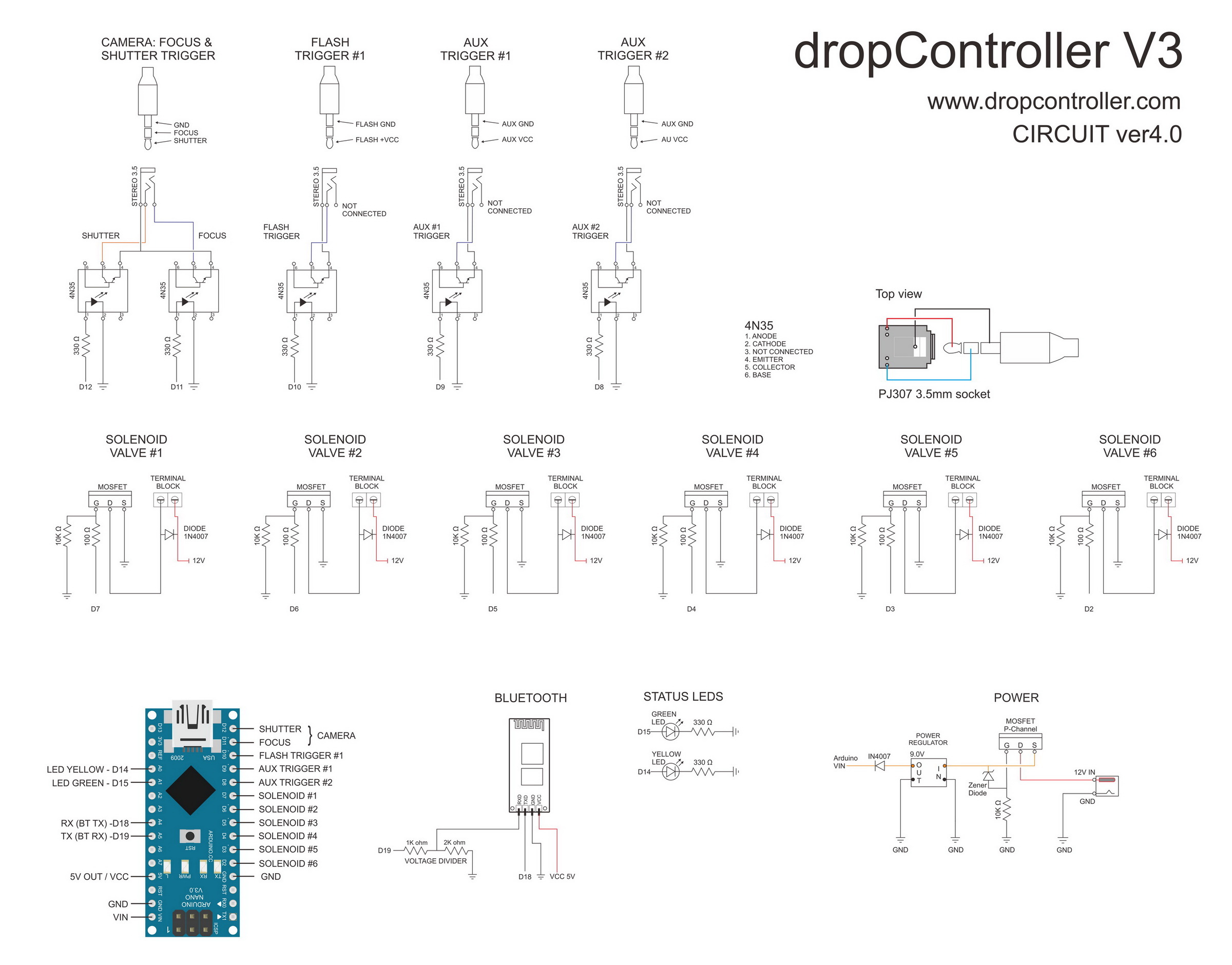
Download a hires image of the above circuit diagram.
PDF here for anybody who prefers a more professional diagram. Schematic created in KiCad.
The full KiCad project can be download from the dropControllerV3 PCB page.
Parts List
- 1 x PCB or Perfboard
- 1 x Arduino Nano
- 2 x 1×15 SIL female header
- 1 x HC-06 (or HC-06 compatible) Bluetooth module
- 1 X DC005 barrel jack socket. 5.5mm OD, 2.1mm ID
- 1 x DC-DC step down buck converter (or LM7808 + capacitors)
- 1 x F9Z24N (or similar) mosfet
- 1 x 1N4740 10v Zener Diode (1N4739 9.1v also suitable)
- 6 x 2EDGK 2P terminal connector (plug) (or screw terminal)
- 6 x 2ERJK 2P terminal connector (socket)
- 1 x 1×6 female header (to connect the Bluetooth module. This can be soldered directly to the PCB/perfboard for a more secure connection).
- 6 x IRLZ44N mosfet (IRL540N also suitable)
- 5 x 6 pin DIL socket
- 5 x 4N35 optocoupler
- 4 x PJ307 3.5mm socket
- 1 x green LED
- 1 x yellow LED
- 7 x 1N4007 diode
- 7 x 1/4w resistor 10K Ohm
- 1 x 1/4wresistor 2K Ohm
- 1 x 1/4w resistor 1K Ohm
- 7 x 1/4w resistor330 Ohm
- 6 x 1/4w resistor100 Ohm (150 ohm also good).
Many of the components (if not all) can be swapped with alternatives. This includes the mosfets, the optocouplers, the sockets, and even the Arduino and the Bluetooth module.
Valve Control & Mosfets
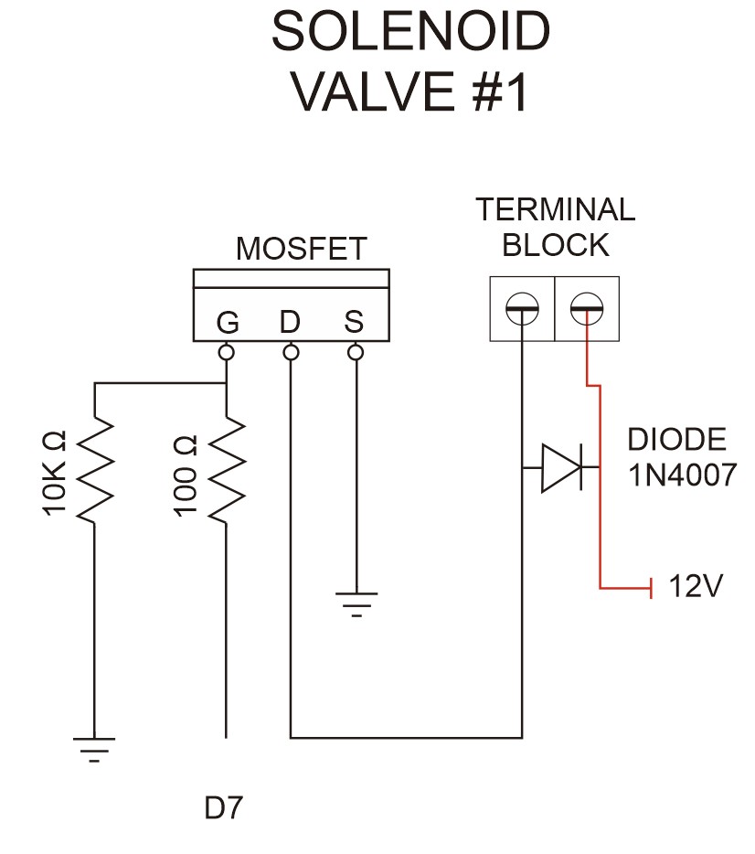
The solenoid valves receive power from VCC in (12v) via the F9Z24N P channel mosfet (the mosfet us is used for polarity protection). The valves are controlled using N channel mosfets which are in turn is controlled by the Arduino. In this way the mosfets are used as digital switches turning the valve on and off.
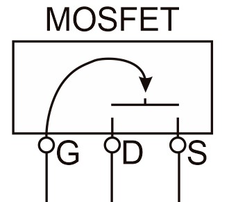
You can think of the mosfet as a digital switch (very simplified overview), when there is a suitable voltage on the Gate pin, current is allowed to flow between the Source and the Drain pins.
I am using IRL540N and IRLZ44N mosfets but there are many alternatives. The mosfet needs to be logic level with a low RDSon at 5V/4.5V and more than able to handle the voltage used to drive the valves (drain-to-Source Breakdown Voltage). Always add a bit more, so aim for over 12v. The IRL540n has a drain-to-Source Breakdown Voltage of 100v so plenty of safety margin.

Mosfets are voltage driven rather than current driven devices and, depending who you ask, where you ask, and which way the wind in blowing, you may be told a resistor on the gate pin is or is not required.
I like to play safe. When a voltage is first applied to the gate pin, the mosfet can act like a capacitor and for a very short time draw quite a lot of current. The 100ohm resistor (150 ohm also good) slows this down a bit and keeps the Arduino from destroying itself.
The 10K resistor pulls the Gate pin to ground when there is no signal from the Arduino and should be included. For one, it prevents the pin floating and causing ghost activity and for two, it stops the mosfet from going in to an undefined state which is basically a resistor and has the potential to burn up.
Camera & Flash Triggers Using 4N35s
The circuit has 4 triggers; one camera (focus and shutter), 1 flash, and 2 AUX. If you don’t plan to use the AUX triggers they can be left out.
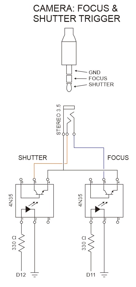
To isolate the camera and flash guns from the main dropController circuit, 4N35 optocouplers are used. These offer some basic protection but are not 100% fool proof.
When used with low voltages such as the dropController and modern digital cameras and flash guns the 4N35s work well but if a large enough voltage is applied to the optocoupler it can short and cause damage.
As with the mosfets the 4N35s are used as digital switches. When a current is applied between pins 1 and 2, current is allowed to flow between pins 5 and 4. The main difference between the 4N35 and the mosfet is that the 4N35 physically separates the 2 sides of the circuit. With the mosfet the ground is common. The 4N35 can control a separate circuit without having contact with it.
Power/vcc
The dropControllerV3 circuit has three voltages; 12v, 8/9v, and 5v. The 12v powers the valves, the 8/9v powers the Arduino, and the 5v powers the Bluetooth module, the mosfets, and the optocouplers.
– 12v is the main power in.
– 9v is the output voltage from the buck converter (or 8v from a LM7808).
– 5v is the output from the Arduino.
Power In
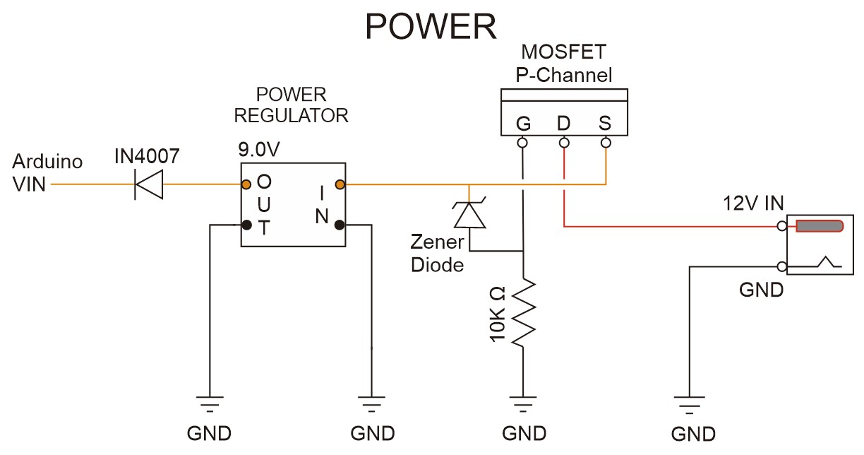

Polarity Protection
A P-channel mosfet is used to offer polarity protection on the vcc in. When the vcc and GND are swapped, the mosfet stops current flowing.
The circuit does not really offer any over voltage protection so keep the vcc in to 12v.
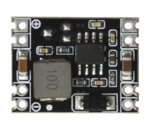
DC-DC Step Down
To drop the 12v to 8v or 9v I use either a LM7808 or a small pre-built DC-DC step down buck converter. The kit contains a step down converter but for DIY a LM7808 is perfectly fine.
I use a specific model of the buck converter for the kits but any step down converter that accepts 12v+ input and allows 8v or 9v out will be OK. Output from the buck converter goes to the Arduino via a diode.
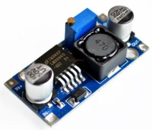
The vcc out from the buck converter/LM7808 goes to the Arduino vin pin. The vin pin can safely accept anywhere from 7v to 12v so, although I suggest to set the buck converter to 8v or 9v, it is not critical to get it exact.
The vin pin on the Arduino connects to an onboard voltage regulator which, to work correctly requires at least 6v and 6v is the lowest you should aim for. A little higher is better.
There is a diode between the buck convertor and the Arduino, this has a voltage drop of around 0.7v so you should have a minimum of 6.7v coming out of the buck converter. I rounded up to 8v and later found nice fixed 9v output buck converters so went up to 9v.
LM7808
Linear regulators like the LM780x range can be used instead of the buck convertor. Due to the diode between power in and the Arduino vin pin, 5v from the common LM7805 is too low and I suggest using the LM7808 which outputs 8 volts. If you use a LM7808 you will also need a couple of capacitors. Something like 300nF on the input and 100nF on the output.
1N4007 Diode
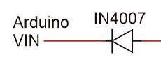
The 1N4007 diode is used for polarity protection for when the Arduino is connected to a computer via USB and an external power supply at the same time.
Bluetooth Module
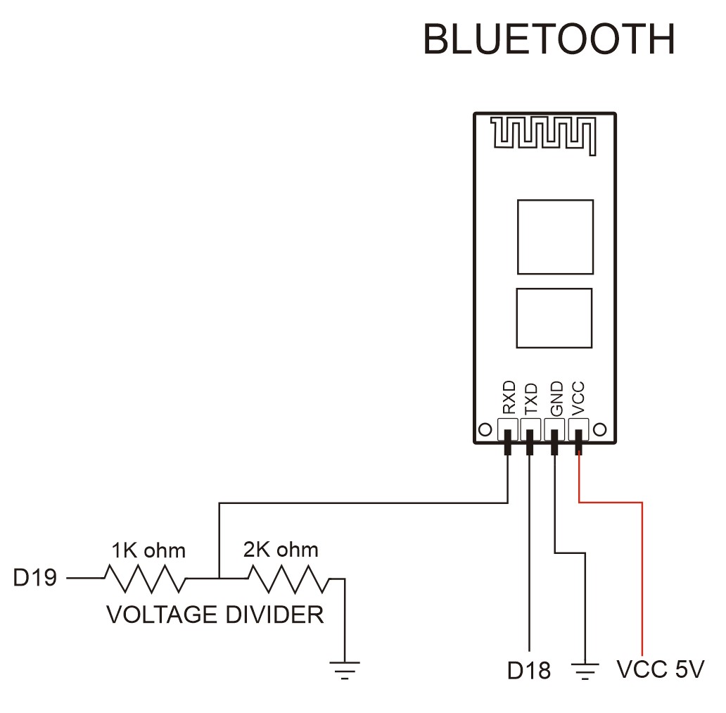
Although the circuit and parts list shows a HC-06, any HC-06 / SPP compatible module is OK.
I recommend only the HC-06 because it is easy to set up. All the modules I have tried have the same default settings so you can use them straight from the tin. The only thing you may want to do is change the name.
There are many different versions of the HC-06 and I believe all will work with the dropController, as will any module that has a Bluetooth Classic BT 2.1/SPP mode and interfaces using UART 8-N-1 at 9600 baud rate.
Due to cost of the HC-06s, I am now using the HC-02. Same manufacturer, same reliability, cheaper.
On many Bluetooth modules (with breakout boards), especially older ones, the RX pin is not 5v tolerant and so a voltage divider is used to reduce the Arduino’s 5v TX pin to 3.3v.
We do not need a voltage converter on the other pin, BT TX -> Arduino RX, as the Arduino will read 3.3v as HIGH (the same as 5v) and so the Bluetooth TX pin can be connected directly to the Arduino RX pin.
Update
Some of the newer module breakout boards (such as the HC01/Wavesen modules) are now 5v tolerant and if you have one of these modules there is no need for the voltage divider. If you are not sure leave it in. It will not effect the circuit, unless it does, then remove it 😉
NOTE: The actual Bluetooth module, the small daughter board, is always a 3.3v device. There are many different breakout boards (the larger mother board) and most do not change the voltage on the RX and TX pins, some do however.
Update 2
The official Waven/HC HC-06 modules are now quite expensive and I have switched to the HC-02. Still from Waven/HC but a bit cheaper. However, any BT 2 SPP module will work.
Note About The Buck Converter and Bluetooth Module
If you plan to use the dropController with a PC only (no Android) then the buck converter + diode and the Bluetooth module are not required. The Arduino will receive power from the computers USB and the valves will receive power from the 12v in.

