Introduction
This is a run through of all the controls and tabs. It is long and mostly boring. While it will give you a good understanding of how powerful the dropController can be is not intended as a getting started guide. If you want to simply get started making drops you are better off with the First Drops guides. Use the dropController a few times, get a feeling for how the dropController works and then come back here to see what else it can do. There are some controls that you will use every time time you make drops and there are some you may never use. That’s fine.
The Five Tabs
The dropController Android app has 5 Tabs; Drops, Settings, Drain, Graph, and About.
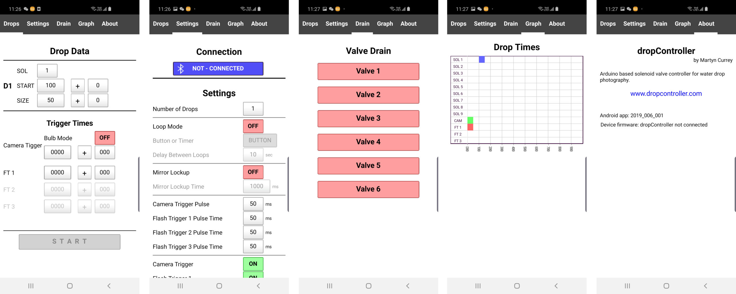
The Drops tab is where you set the drop times and sizes. The drops page also has the controls for the camera trigger and flash triggers.
The Settings tab contains the general settings (things that normally only need doing once), the connection controls, and the valve drain controls.
The Drain tab has controls that allow you to open a valve for draining.
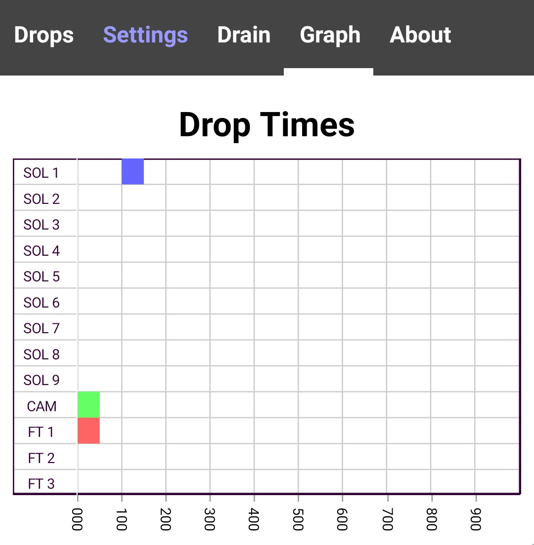
The Graph tab shows a chart of the drop settings. This helps visualize the drop sequence.
The About tab gives basic information about the app version and, after connection is made, the dropController firmware version.
Settings Tab
Connecting to the dropController device has already been covered so I will skip the connection process.
 I’ll start with the Settings tab simply because there are certain things that need to be set before starting with the drops and it will help make the other tabs make sense.
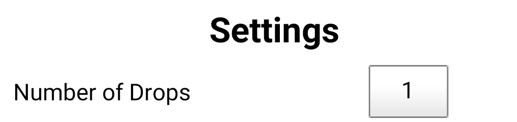
Number of Drops

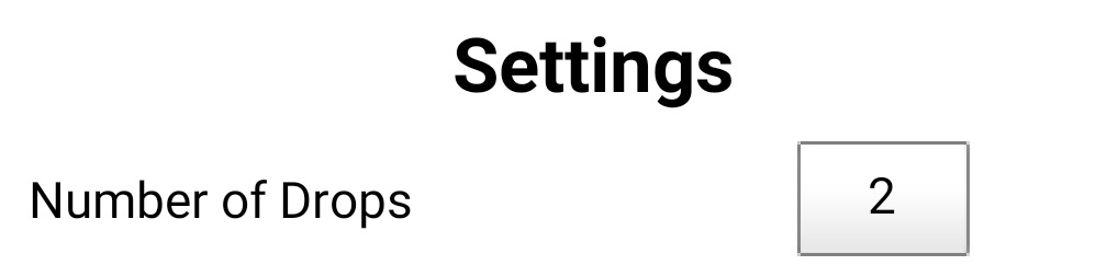
Selects the number of drops to use; from 1 to 9. Clicking the selection button brings up a list allowing you to pick the number of drops. The drop controls on the Drop Data page then become active.
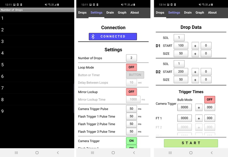
With 2 drops selected the controls for 2 drops are active on the Drops tab
Loop Mode

Loop Mode is covered in detail later.
Trigger Pulse Times
The trigger Pulse Time is the time the trigger signal is active. It is not the time the trigger is performed.
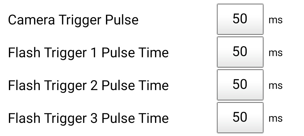 These are not the times the triggers happen but how long the trigger signal is on.
Times are in milliseconds and 50ms is a good default time. Leave them at 50ms unless you have issues.
Most people will never need to change the trigger pulse times. They were added to a very early version of the dropController to allow me to use an old flash gun that required a fairly long trigger pulse and I simple left them in.
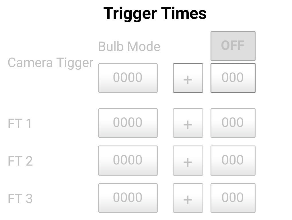
Camera and Flash Triggers
The trigger controls turn on and off the camera and flash triggers.
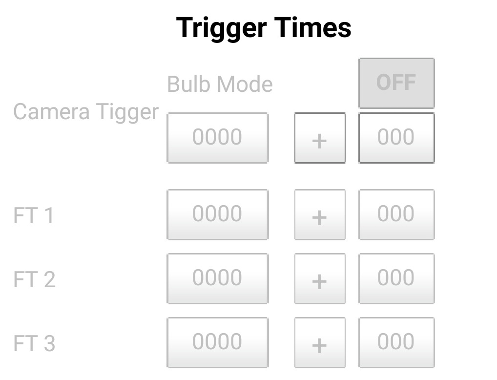
When the trigger is OFF the controls on the Drop tab are greyed out/inactive.
The triggers are covered in more detail in the Drop Data section.
Sounds
![]()
Turn sounds on and off.
Reset
![]()
RESET resets all the settings and drop data. It’s like a return to factory default setting.
The Drops Tab
 Here is where all the action takes place, where the times for the drops and triggers are entered.
There are three sections;
– the drop data settings
– the trigger settings
– the START button.
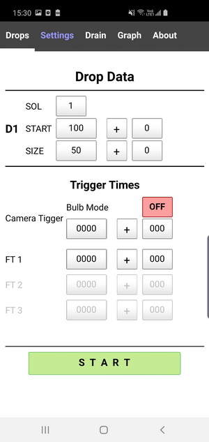
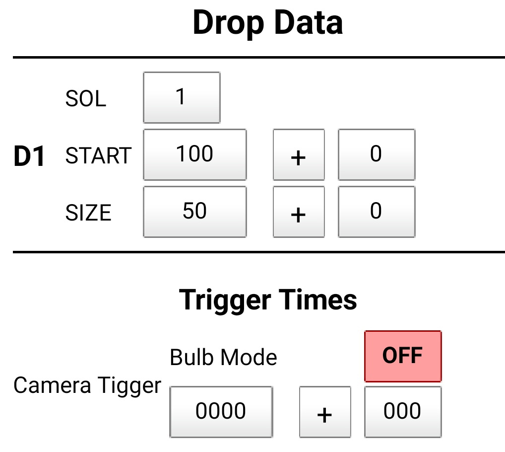
Drop Data
Each drop has several properties:
| SOL | 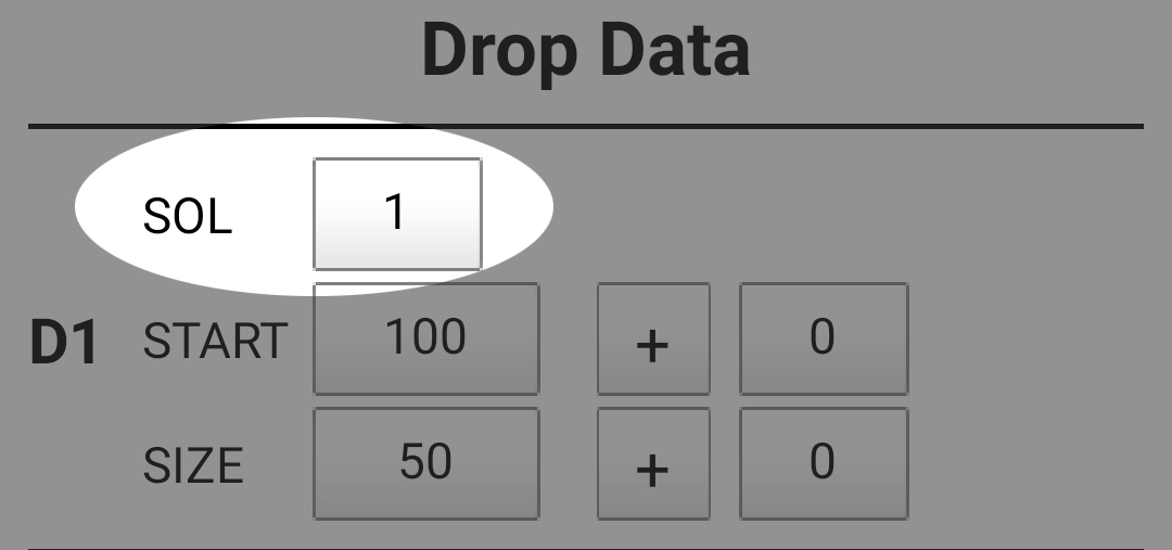 |
The solenoid valve to use (from 1 to 6). The number relates to the valve connection port on the dropController. |
| START |  |
The drop start time in milliseconds. |
| START delta +/- | 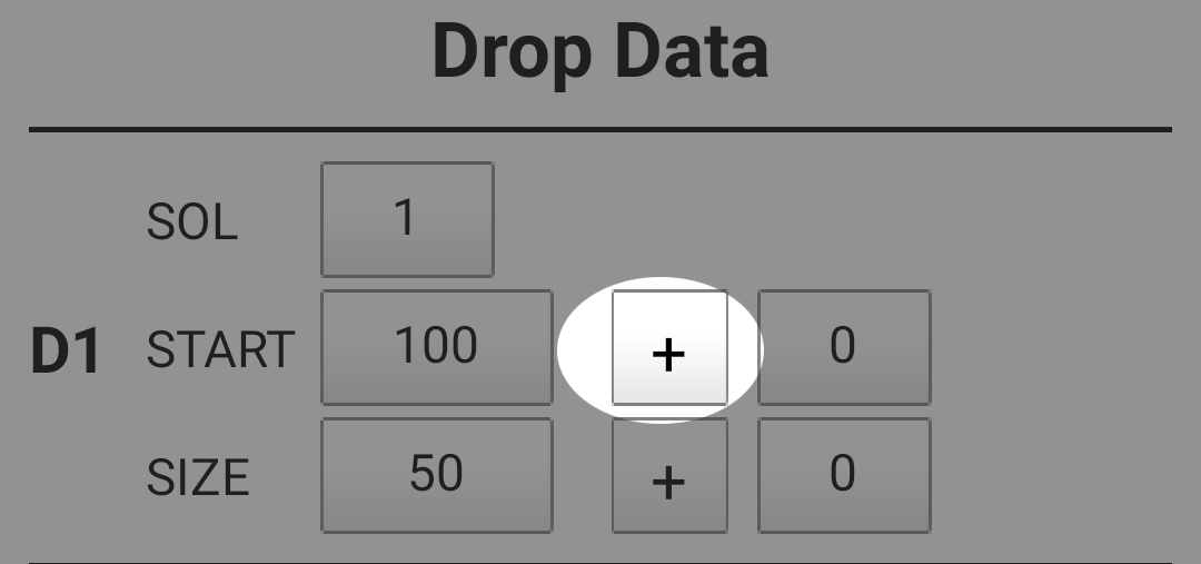 |
START time delta. Increase or decrease the start time (used in Loop Mode only). |
| Delta Time | 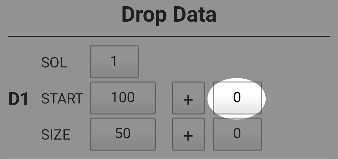 |
How much time (in milliseconds) to either increase to decrease the drop start time. 000 is off. Max is 999 |
| SIZE | 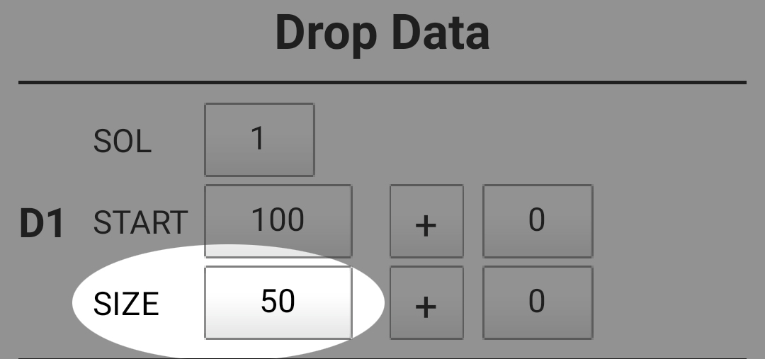 |
This is the amount of time (in milliseconds) the valve is open. In this guide I use milliseconds to describe the drop size. For example, a drop size of 30ms. |
| SIZE delta +/- | 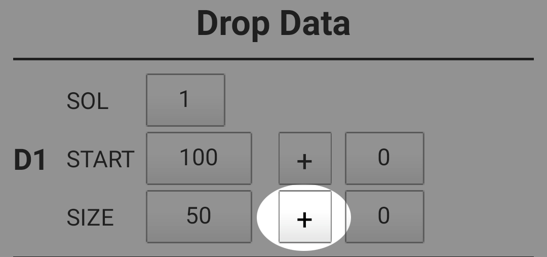 |
Increase or decrease the size. Loop Mode only |
| Delta Time | 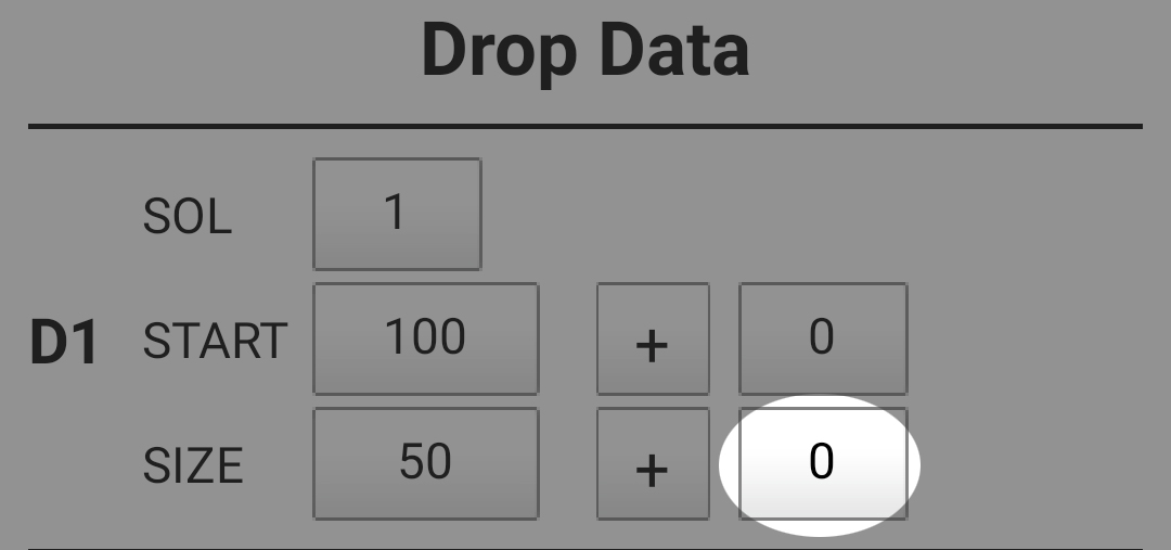 |
The amount of time (in milliseconds) to increase or decrease the drop size on each iteration of the loop. 000 is off. Max size is 999. |
When using Loop Mode you can increase or decrease the drop start time and the drop size on each iteration of the loop.
Number of Drops
The number of drops can be set on the Settings tab. After setting the controls for the drops become active.
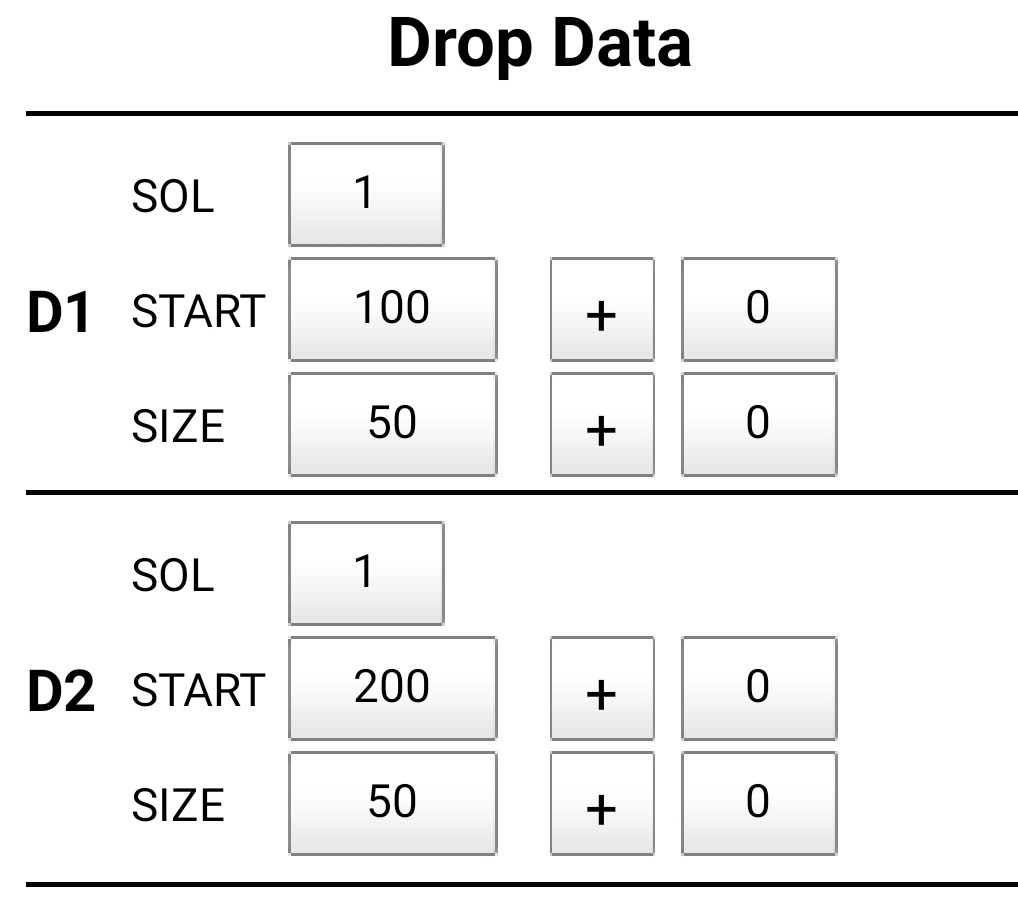
Up to 9 drops can be selected.
Triggers
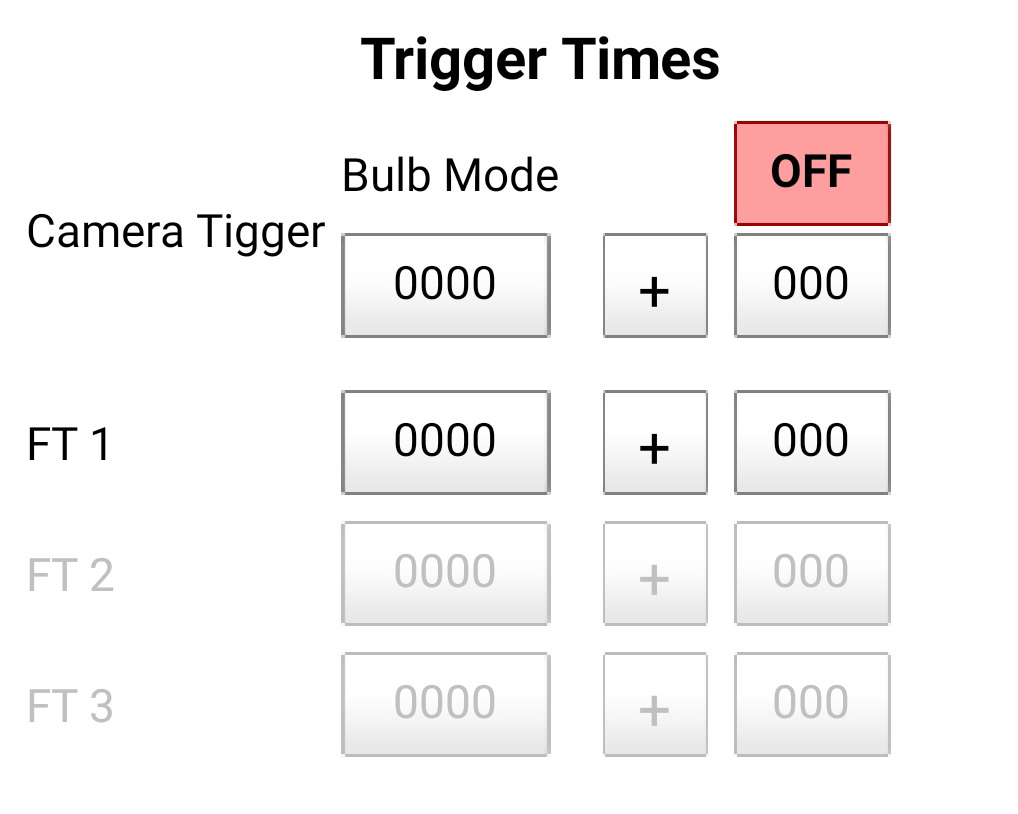
Shutter Trigger
Flash Trigger 1
Flash Trigger 2
Flash Trigger 3
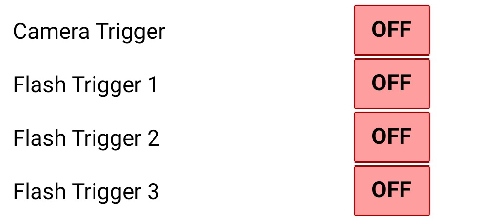
The camera and flash triggers can be turned on and off in the Settings page.
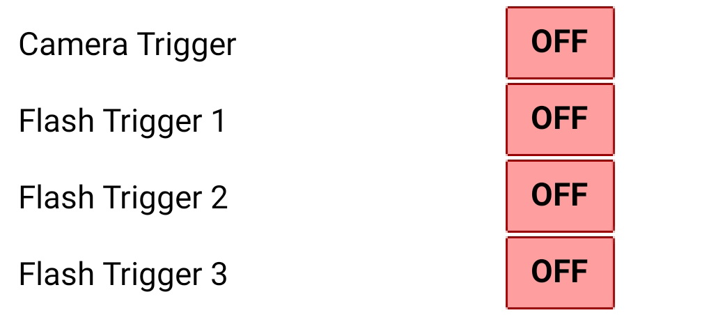
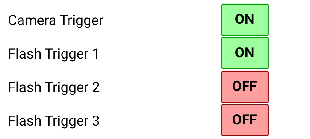
All off
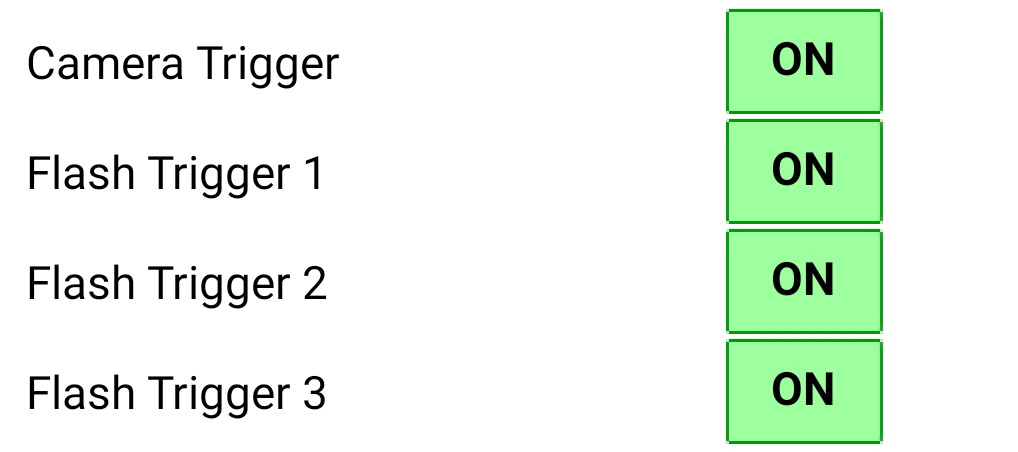
All on
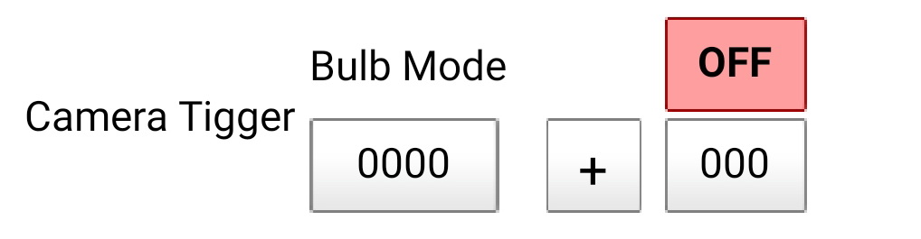
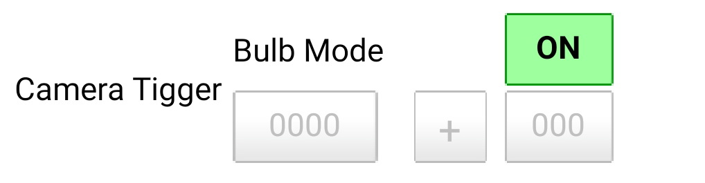
Camera Trigger
![]()
The Camera Trigger has 3 modes; OFF, ON + Shutter (Bulb OFF), ON + Bulb
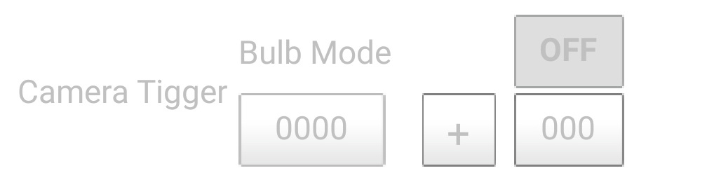 When OFF the controls are inactive and the camera shutter trigger signal is not used.
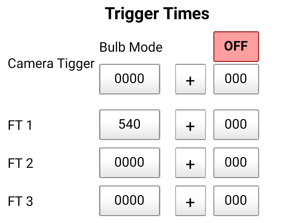
 When the camera trigger is ON and Bulb Mode is OFF the camera trigger properties are active. Enter the time (in milliseconds) you wish to activate the camera shutter.
A delta valve can be used to change the camera trigger time when using Loop Mode. Loop Mode and delta values are explained in detail later.
 When in Bulb mode the camera trigger properties are inactive.
When using Bulb Mode the shutter is opened just before the drop sequence starts and closed just after the sequence finishes. To use Bulb Mode your camera must support bulb mode and be in bulb mode.
Ideally, the camera should be in manual mode or bulb mode when used with the dropController.
Flash Triggers
There are 3 Flash triggers and each trigger works in the same way.
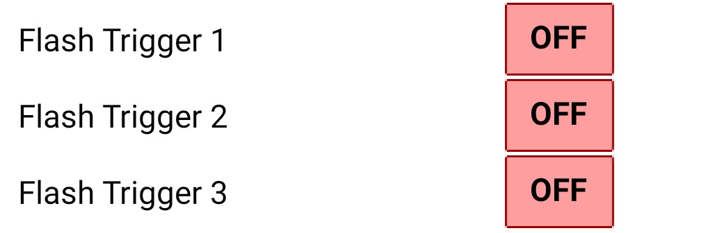
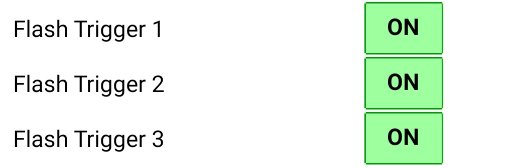
Each flash trigger can be turned ON or OFF on the Settings page. When OFF no trigger signal is sent to the flash.
When the flash trigger is ON the flash trigger controls are active. When active the flash trigger time (in milliseconds) can be entered. When using Loop Mode a delta value can be used to alter the trigger time on every iteration of the loop. Loop Mode and delta values are explained in detail later.
Normally only one Flash Trigger is used. When using multiple flash guns, the flashes should all be connected to a single trigger. The additional flash triggers are designed to be used to fire flashes at different times, not to fire separate flashes at the same time. For more details about using multiply flashes see Using Multiple Flashes.
The START Button
When the app is not connected to the dropController the large START button is grey and inactive. When the app is connected the START button turns green and becomes active.
![]()
![]()
When connected, clicking the START button tells the app to send the drop data to the dropController device. Depending on which mode you are using, Single Sequence Mode or Loop Mode, different things happen.
In Single Sequence Mode the data is sent immediately to the dropController and the drops are created straight away. In Loop Mode the Loop Page opens and waits for the user to start the sequence.
Single Sequence Mode
The app is in Single Sequence Mode whenever it is not in Loop Mode.
Whenever Loop Mode is OFF the app is in Single Sequence Mode.
In Single Sequence Mode, a single drop sequence is created. On clicking the START button the drop data is sent to the dropController and the START button changes to ACTIVE.

 On the dropController device, the yellow LED turns off and the green LED turns on. The green LED shows that a drop sequence is active on the controller.
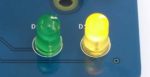 When the sequence is finished the green LED goes out and the yellow one comes on again.
In the app the START/ACTIVE button returns to START
In Single Sequence Mode delta values are ignored.
Loop Mode
Loop Mode is the heart of the dropController and it is Loop Mode that makes getting collisions so easy.
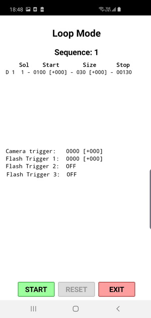
When Loop Mode is ON, when the large START button is clicked, the Loop Page opens
To activate Loop Mode, in the Settings Tab set the Loop Mode OFF/ON button to ON. When ON the Loop Mode controls become active.
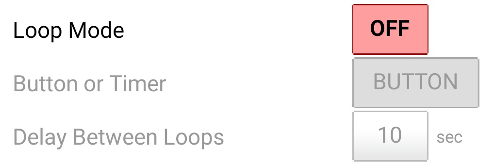

There are two methods used to start the next sequence, either a TIMER or a BUTTON click.
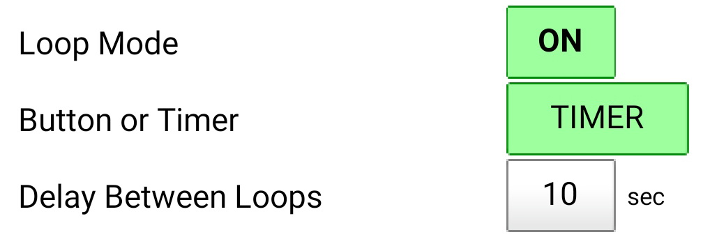
TIMER
BUTTON
When using TIMER, a count down delay is used. The Wait Time is how long the app waits before starting the next sequence. The time is in seconds.
You will need to experiment to see what wait time suits you. I generally use around 10 seconds. This allows time for the water in the tray to settle and also allows time to move any bubbles out of the way.
If you find you are constantly removing bubbles or adjusting things then it is probably better to use the BUTTON option.
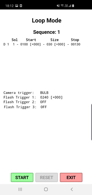
When using BUTTON, the app waits for the user to click the Loop Page START button.
 The Loop Page with a timer counting down. The next sequence will start when the timer reaches 0.
 The Loop Page waiting for the small START button to be clicked. The next sequence will start when the button is clicked.
When TIMER is selected a timer is used to delay the next drop sequence. When BUTTON is selected, the next sequence is held until the user clicks the small START button.
TIMER
When using the TIMER option the first drop sequence is started as soon as you click the START button. After the first sequence is completed the timer will start a countdown and when it reaches zero the next sequence will start automatically.

While the timer is counting down, clicking the STOP button pauses the app at the current sequence number. Click START to continue. Clicking RESET resets sequence number back to 1.
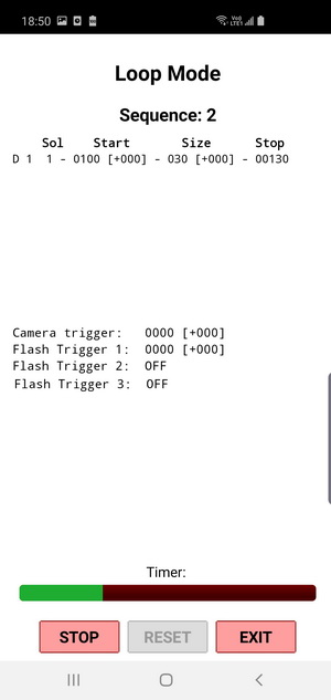
The app has been paused at Sequence 4.

RESET resets the sequence to 1 and the drop data to the start values.
Delta Values
Delta values are values that change inside a loop on every iteration of the loop. For the dropController, this is the drop start times, the drop sizes and the trigger times. Any value that has a INC/DEC [+/-] control has a delta value.
The INC/DEC [+/-] button allows you to either add to or subtract the delta value. INC for increase and DEC for decrease.
For example, on every iteration of a loop you can change the drop start time, make the drop smaller or bigger, and move when the flash fires.
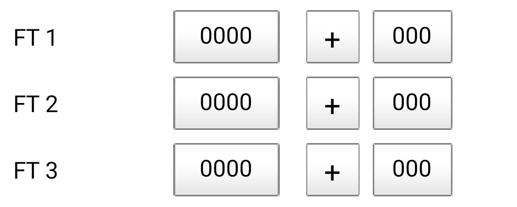
 Here, even though Loop Mode is ON, the INC/DEC times are set to 000 so they have no effect. The drop sequences will loop but the times will not change.
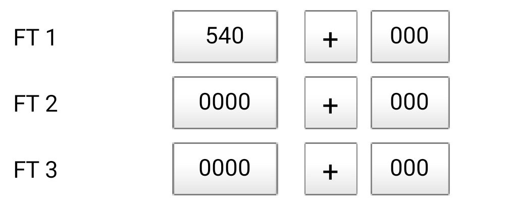
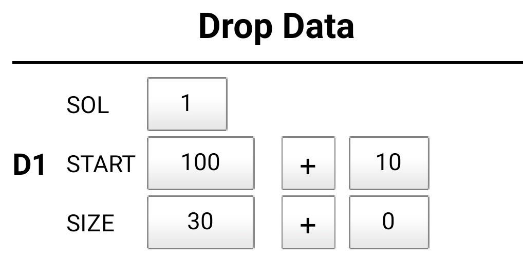 Here a 10ms delta valve has been added to the start time. This means Drop 1 will start 10 ms later every sequence (or iteration of the loop).
– On the first sequence, the drop will start at 100 ms,
– on the second sequence it will start at 110 ms, and
– on the third it will start at 120 ms and so on.
There is no size delta value so the drop size will not change.
Loop Page Labels
The Loop Page shows the drop data for the active drops
| SOL | The solenoid valve being used. |
| START | The drop start time with the delta value in square brackets. |
| SIZE | The drop size with the size delta value in square brackets. |
| STOP | The drop stop time. This is calculated by the app. |

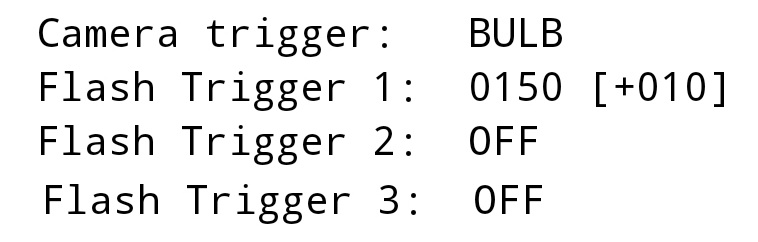
| CT: | Camera Trigger. Set to trigger at 0000. No delta |
| FT1: | Flash Trigger 1. Set to trigger at 2400ms. No delta. |
| FT2: | Flash Trigger 2. OFF |
| FT3: | Flash Trigger 3. OFF |
Delta Values In Use
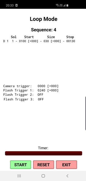
Let’s see a delta value in use. In the following example I am making the Flash Trigger 1 fire at a slightly later time each loop/iteration.
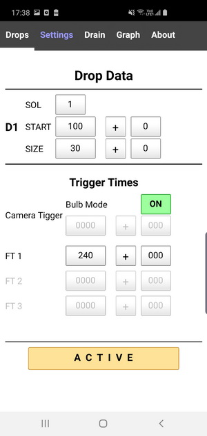
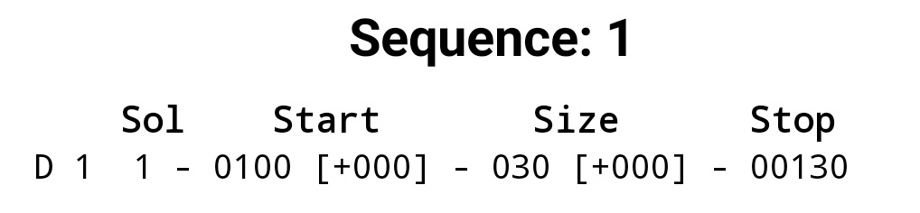
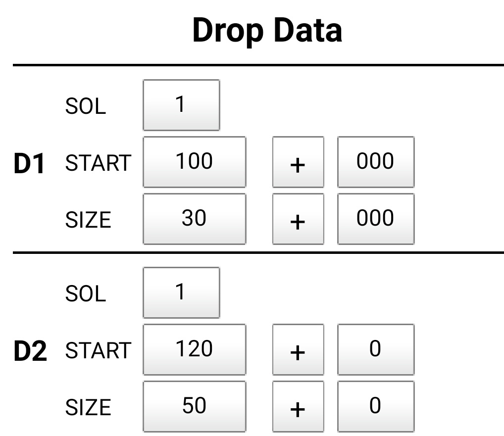
 There is one drop which is on SOL 1; the start time 100, start time delta is 000, size 30ms, size delta 000.
The Camera Trigger is on and set to Bulb Mode.
A single Flash Trigger is active and set to 150ms with a delta value of + 10ms
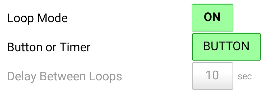 Loop Mode is on and the delay method is BUTTON
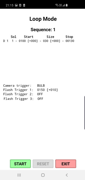 Since Loop Mode is ON, when the START button is clicked the Loop Page is displayed.
Click the START button, this sends the drop data to the dropController device and while the drop is being made the button changes to ACTIVE.
![]()
![]()
When the sequence is finished the button changes back.
Every time the START button is clicked the next sequence is sent to the dropController and any value with a delta is updated.

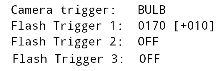
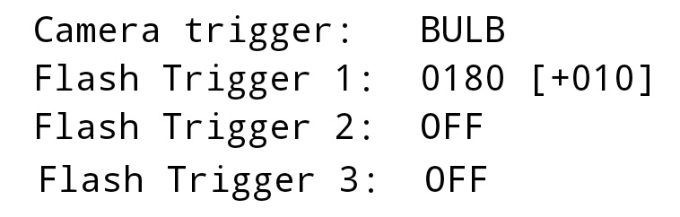
Here you can see Flash Trigger 1 increase 10ms every loop
What does the above do? If you were to run these setting you would capture a falling drop starting from just under the valve.
Delta Value Limits
The times that are changed due to a delta value cannot go outside of their normal range. If the value exceeds these limits it is set to the limit.
For example, the drop start time has a minimum start value of 0 and a maximum of 9999. If a delta value tries to make the start time lower than 0 then it is set to 0. If a delta value tried to take the start time beyond 9999 then the start time is set to 9999.
To explore delta values further see the First Drops Part 1 and First Drops Part 2 guides.
Drop Data Error Checking
In the current version of the Android app there are no checks on the drop data values. This means it is possible to have overlapping drops on the same valve.
 Here the 2 drops use the same valve and have overlapping times. This means it would produce 1 drop sized 70ms.
The is fairly easy to spot when looking at the Drop Data page but hard to find when it is caused by delta vales.
Graph Tab
The Graph page shows the drop times and trigger times in chart form. This aids visualizing the drop times and is especially useful for more complex sequences.
 The first time you use the app the drop times are very basic and the graph doesn’t show much.
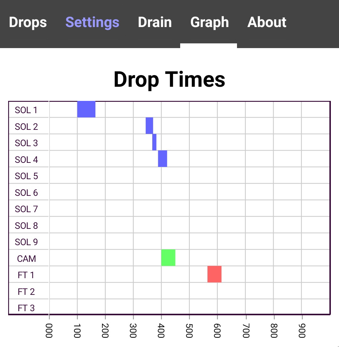 Once you have started to enter drop data the Graph gets a little more interesting.
Here we have 4 drops and the flash set to fire at 564ms.
The shutter is set to 1/2 second exposure which means the shutter will be open from 400ms to 900ms.
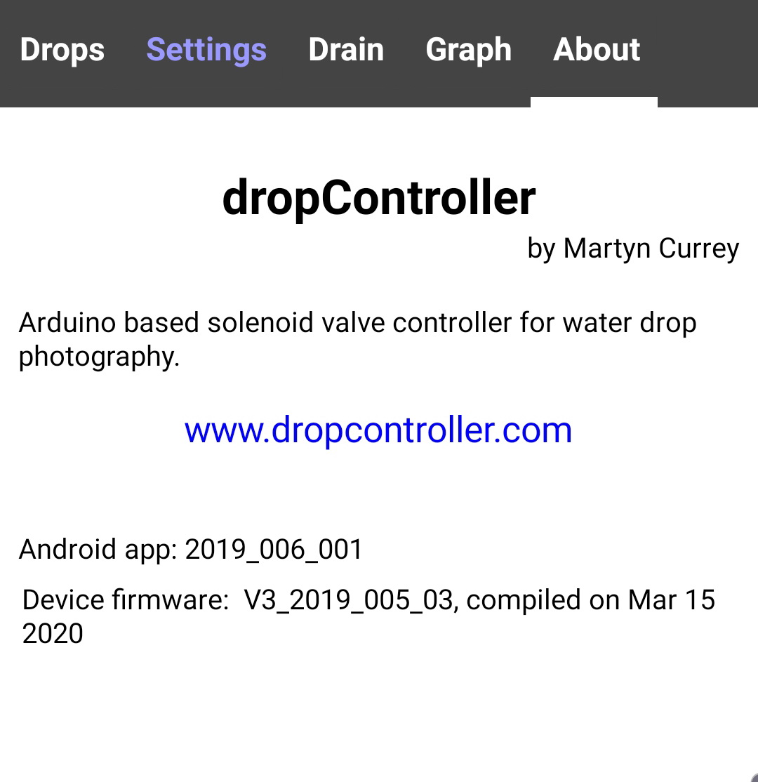
About Tab
The About Tab shows the app version, the dropController device firmware version.