Here are the steps for building your own 3 valve dropControllerBT on perfboard. This is the same circuit as the breadboard version except there are no trigger LEDS. I felt they were not really necessary and I can add them later if I change my mind.
Circuit Diagram
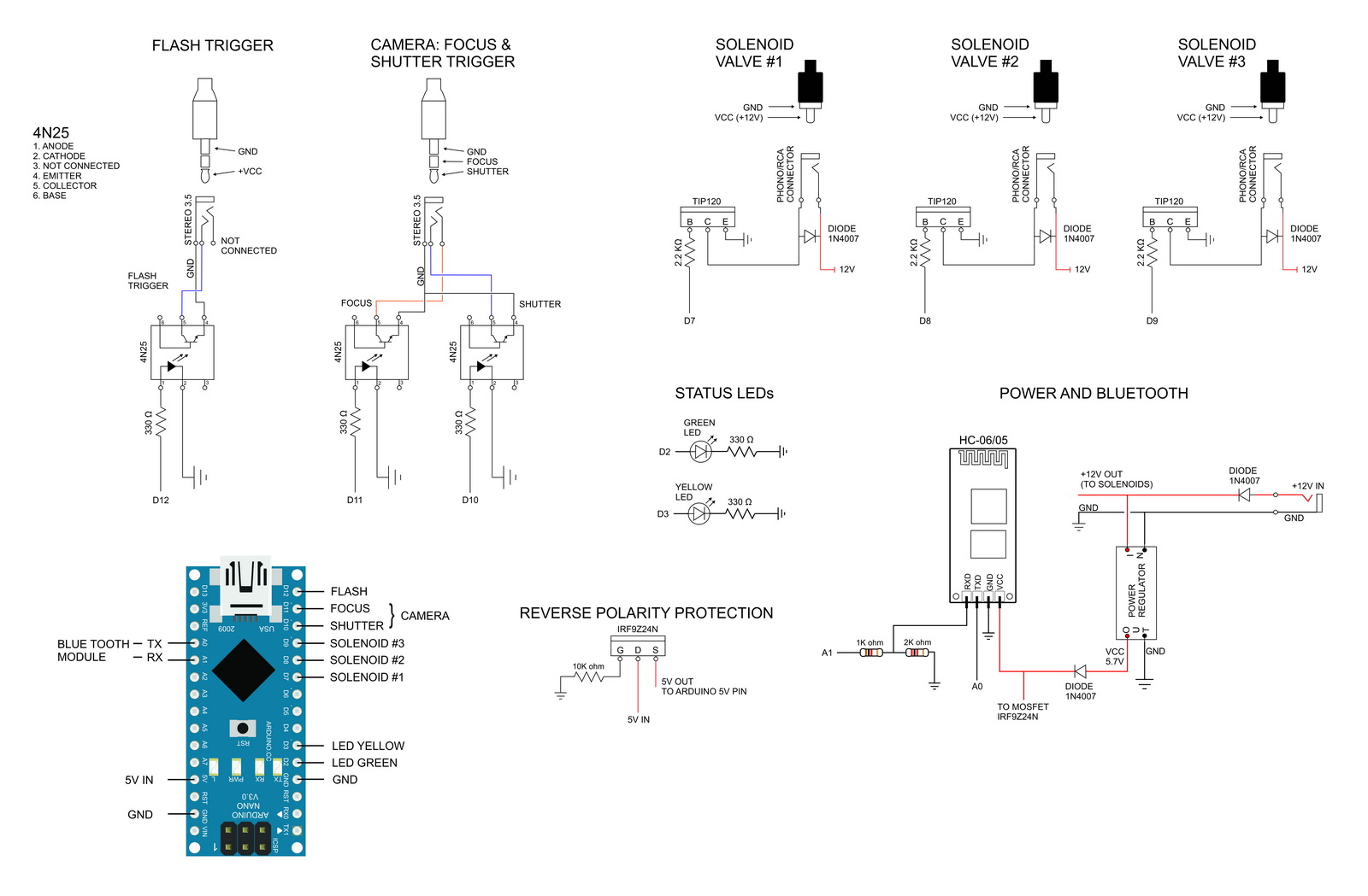
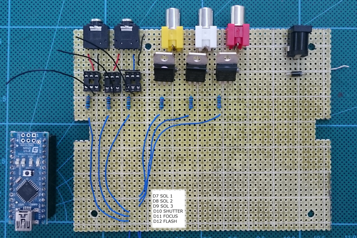
Arduino Pins

Parts List: dropControllerBT Perf Board Version
Case / project box
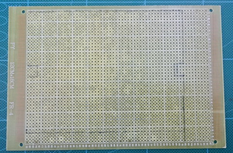
Perf Board x 1
Various wires
Arduino Nano x 1 (or any type of AVR based Arduino)
HC-06 Bluetooth module x1 (HC-05 can also be used)
DC-DC step down power supply x 1 (can also use a LM7806 based circuit)
LEDs x 2
– 1 x Green LED for status – waiting
– 1 x Yellow LED for status – active
3.5 stereo sockets x 2
RCA/Phono sockets x 3
Power socket x 1
4N25 optocoupler x 3 (Anything similar also suitable)
TIP120 x 3
F9Z24N mosfet x 1 (or similar)
330 ohm resistor x 5
1K ohm resistor x 4
2K ohm resistor x 1
2.2K ohm resistor x 3
10k ohm resistor x 1
1N4007 diode x 8
3.5mm jacks to connect to the camera and shutter leads
RCA/Phono jacks to connect to the solenoid valves.
You will also need solenoid valves, a power supply and an Android device.
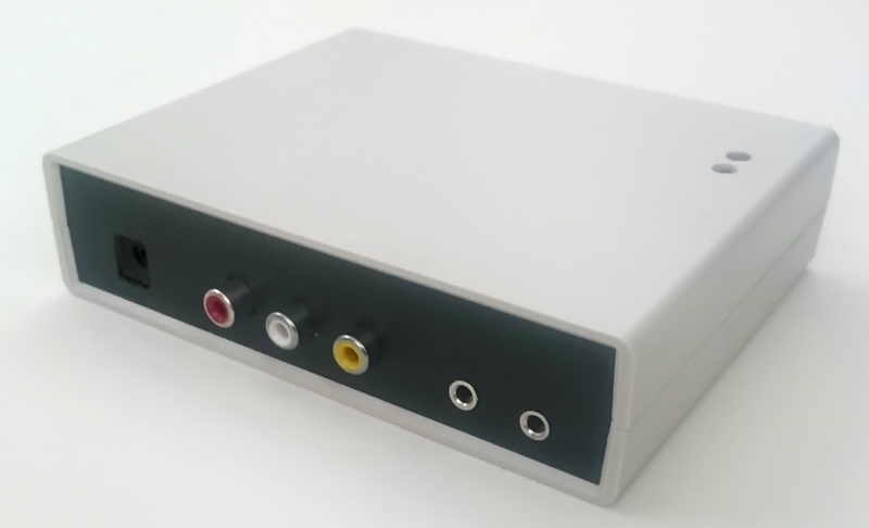
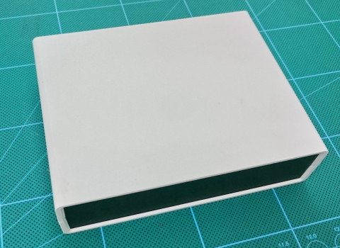
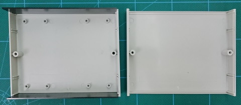
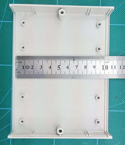
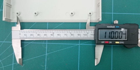
Project Box
I bought a 14cm x 11cm x 3.5cm box for the final project.
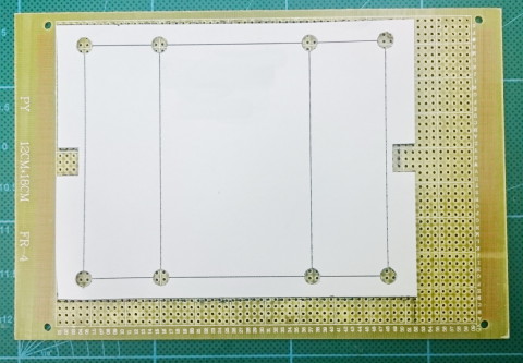
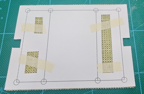
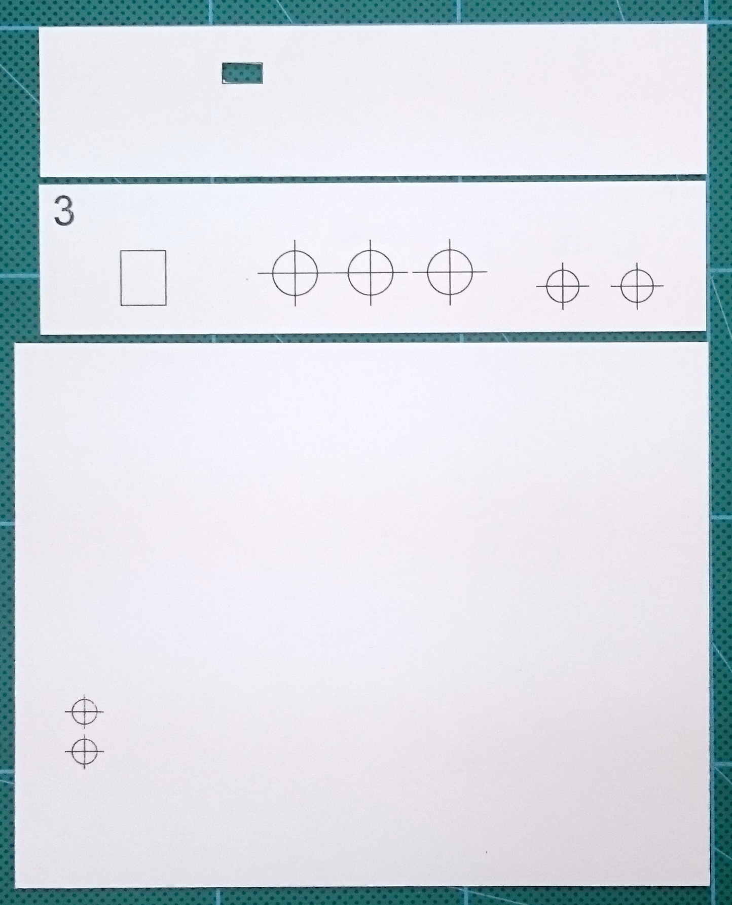
Board Template
My first step was to create a template for the project box.
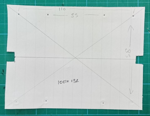
Once I had a rough sketch I created the final template on the computer. To check that everything was OK I cut out and tried it.
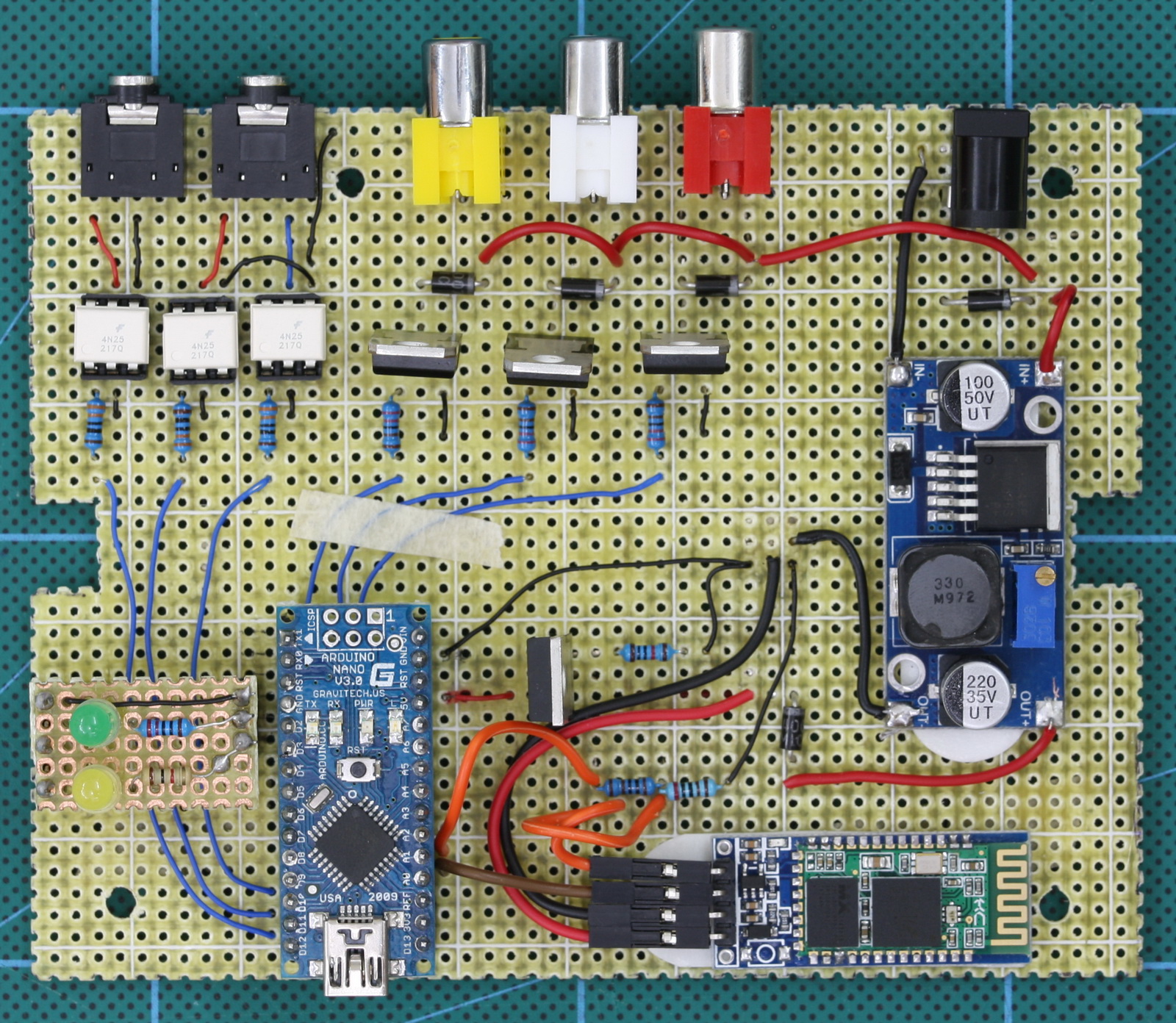
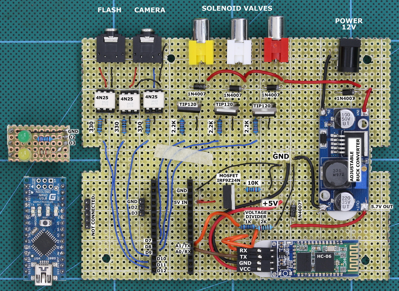
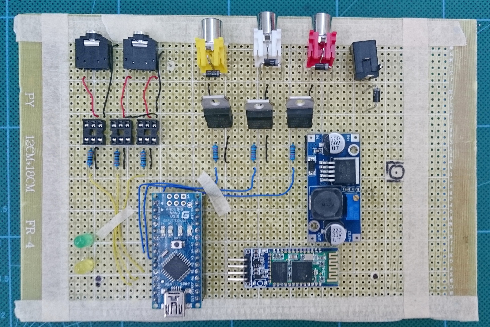
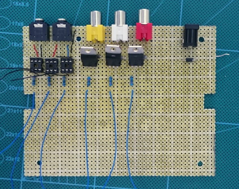
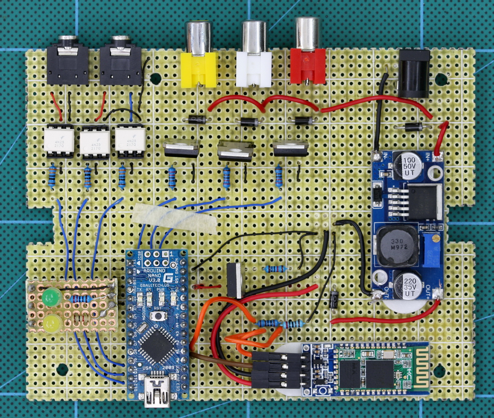
Board Layout
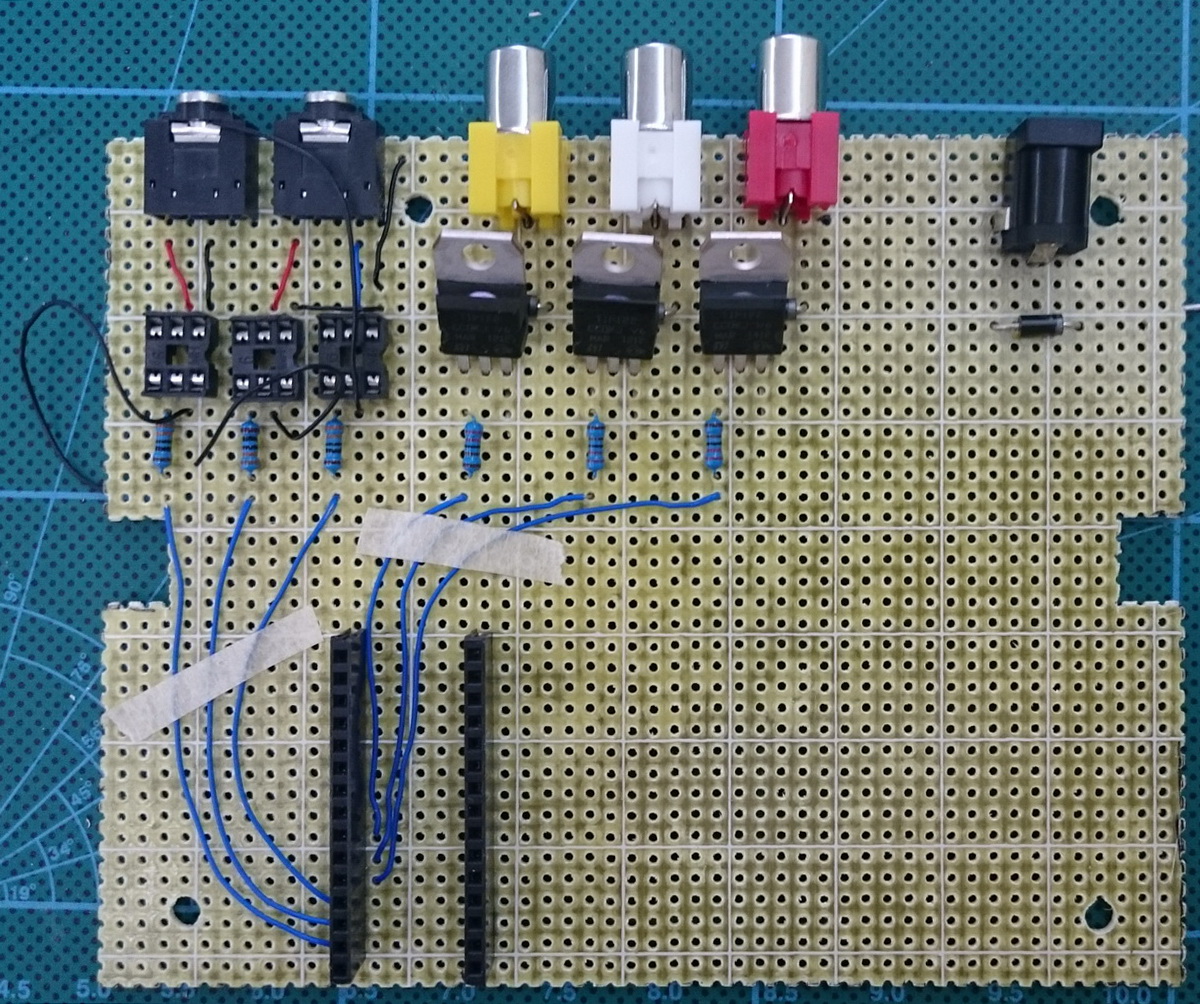
Before starting to solder everything together I did a basic layout to check where the components would be. Nothing is connected at this point, it is simply to check the layout. This also gives me something to copy when actually making the circuit.
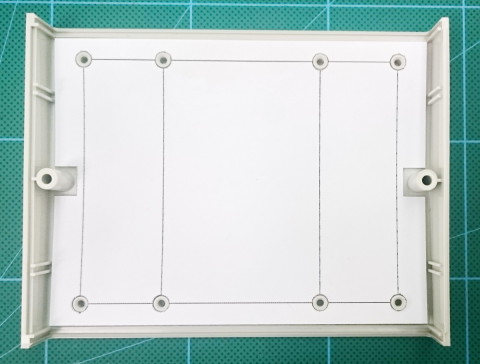
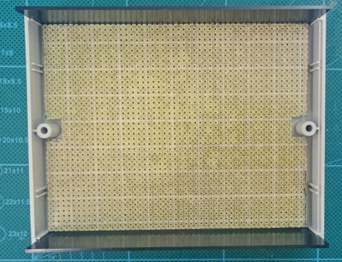
Cutting the Perf Board
Trace round the template keeping to lines that run through the centre of the holes. This makes things easier when cutting.
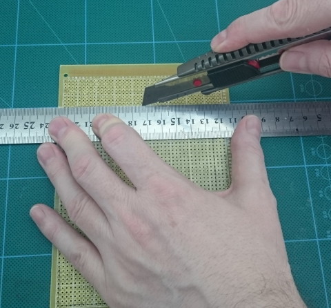
Scoring with a sharp knife is a clean and easy way to cut the perf board. Score both sides of the board through the centre of the holes. Then gently bend. Start at one end and slowly work along. Take your time and try not to force it,
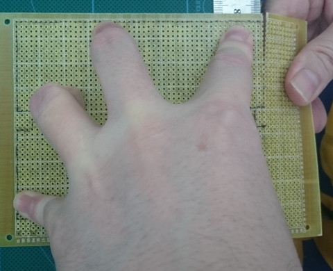
Once the perf board is ready make sure it fits the project box.
Attach the template to the board and drill the screw holes.
If you want a clean finish you can sand the edges. I didn’t need to do this though.
Construction
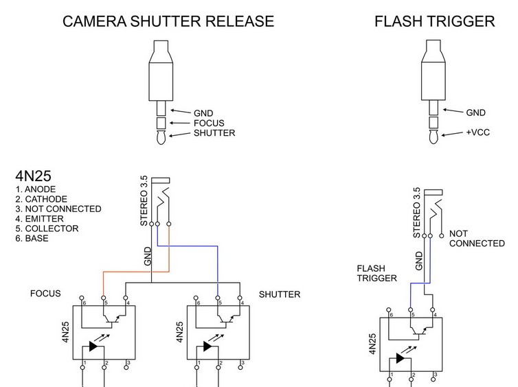
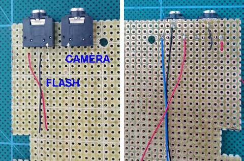
3.5 Stereo Sockets
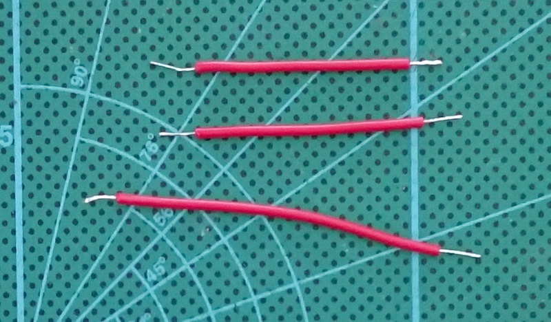
The stereo 3.5 sockets are used to connect to the flash and the camera
The flash uses only 1 channel of the socket and so has only 2 wires. The camera uses both channels; 1 for focus and 1 for the shutter and so has 3 wires.
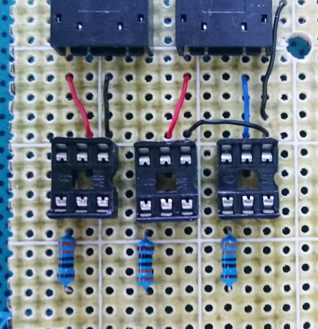
Place the 3.5 sockets
Place the sockets for the opto-couplers
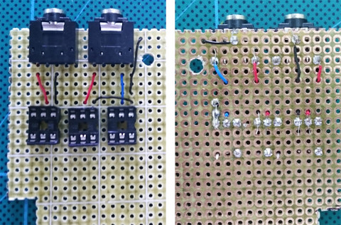
Add resistors
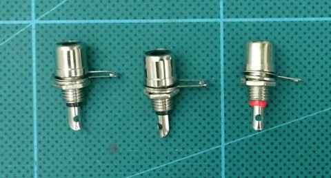
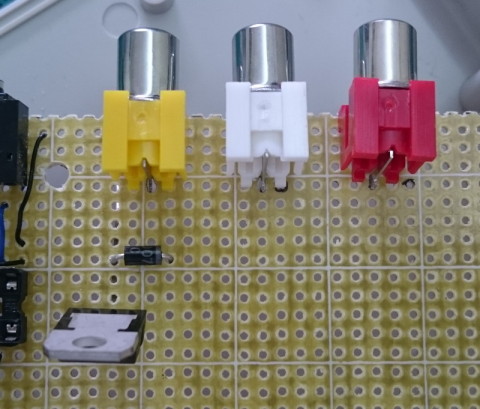
Phone/RCA Sockets
These are used to connect to the solenoid valves. The sockets I have do not fit perf board so I had to create larger holes.
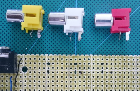
I am using board mounted RCA sockets but you can also use sockets that fit in to the back plate.
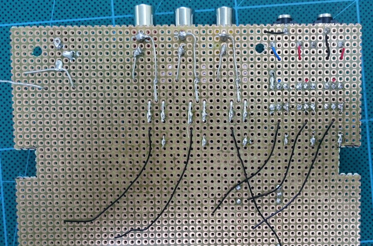
Here is how the socket, the diode and the TIP120 connects together.
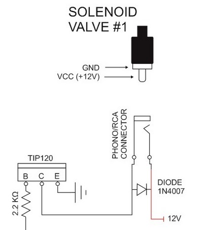
Place the RCA sockets and the diodes
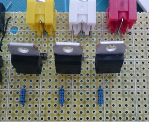
Then add the TIP120s (I am actually using TIP122s because this is what I have) and join the centre pin of the TIP120 to the diode and to GND on the socket.
Add resistors to the B pin of the TIP120s
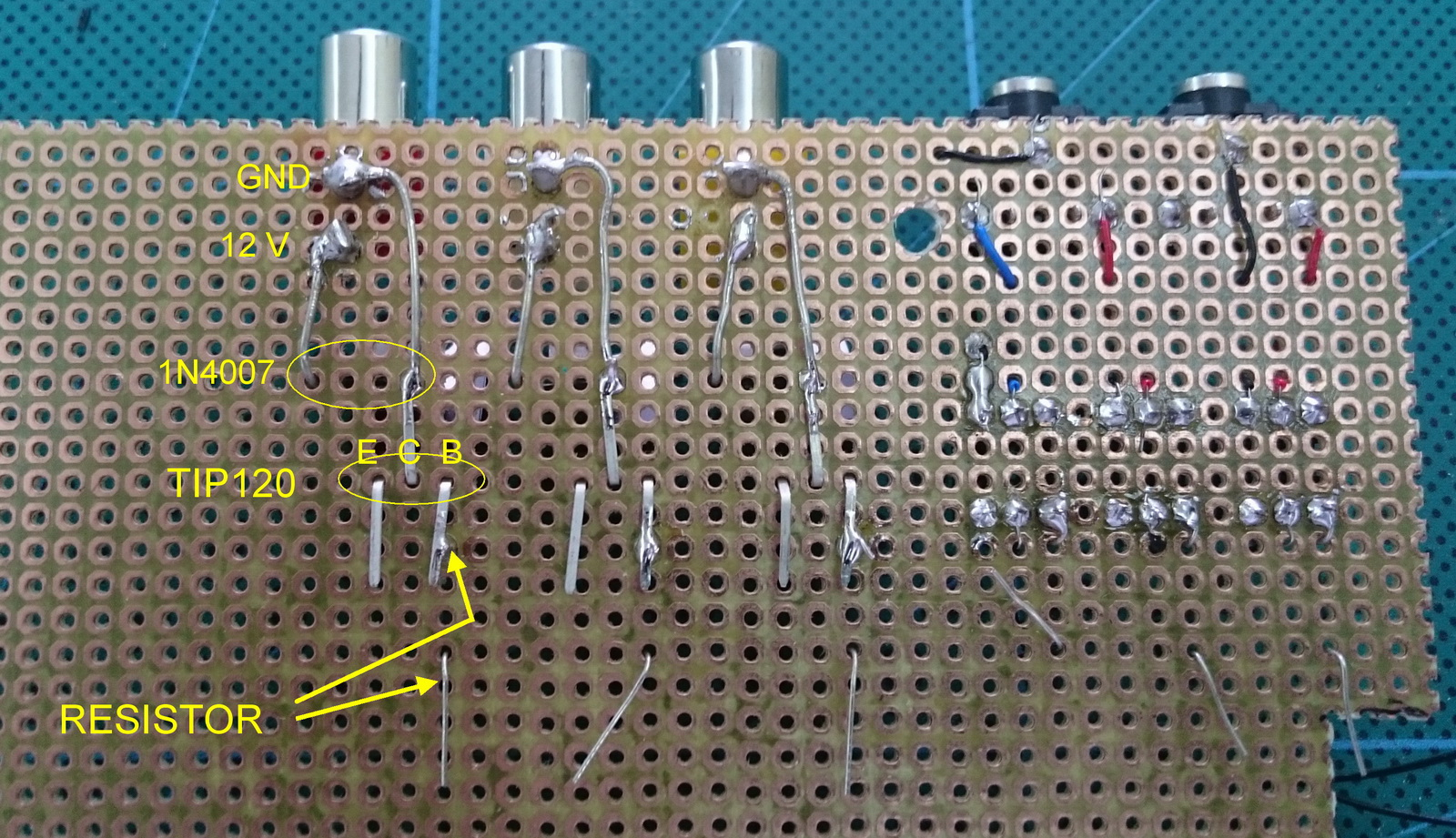
The TIP120 C pin (centre pin) goes to the GND on the RCA socket.
The 1N4007 diode sits across the RCA socket connections.
The TIP120 E pin goes to a resistor and then to the Arduino.
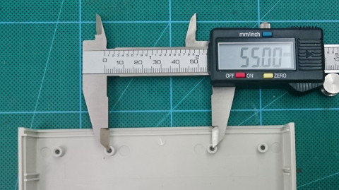
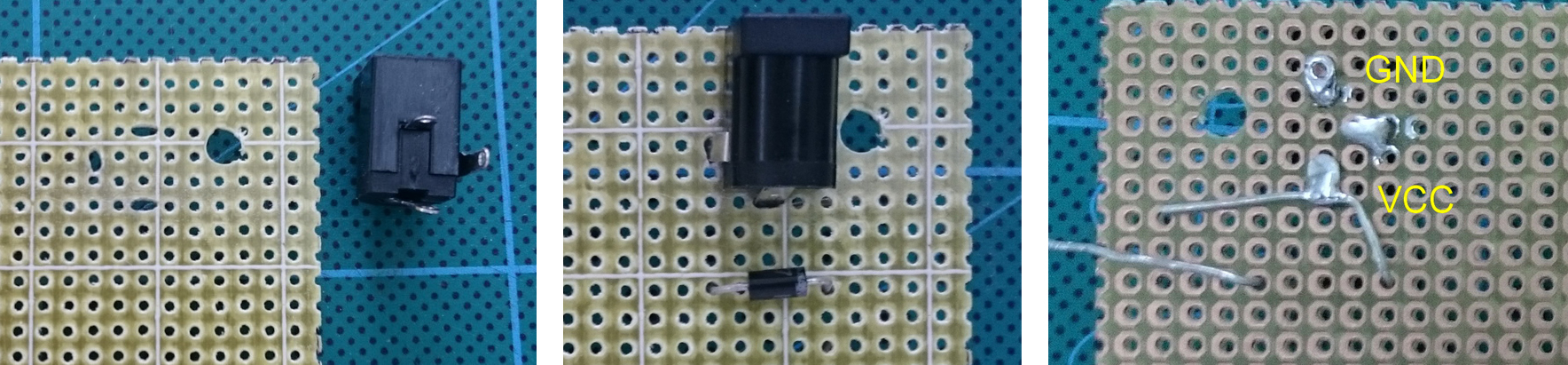
Power Socket
The power socket is not designed for perf board so, like the RCA sockets, I had to make larger holes.
Diodes like the 1N4007 conduct electricity in one direction only and help protect the circuit should the power supply be connected the wrong way-a-round.
Leads to the Arduino
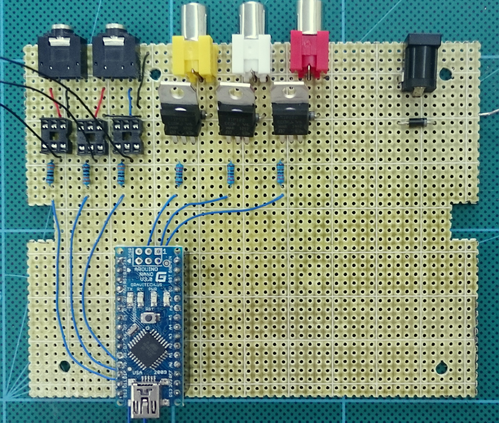
Place the wires to the applicable holes and start to solder the socket that holds the Arduino.
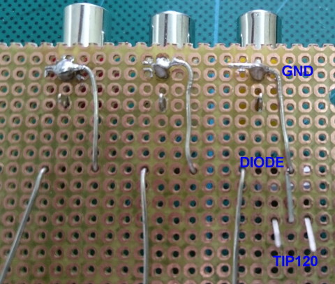
GND Wires
Add GND wires to the TIP120s.
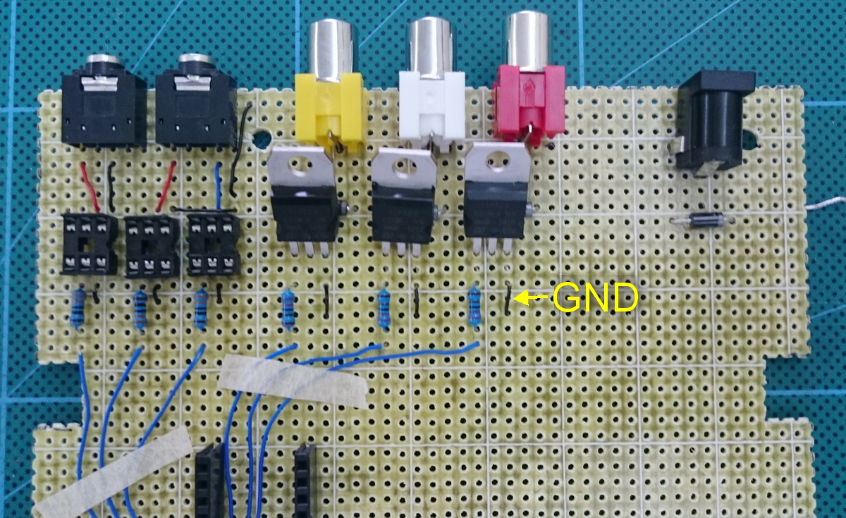
Not really required but I looped the GND wire to the top of the board to clearly show which pins are GND.
12V in Wires
Connect the +12V pins on the RCA sockets to the 12V in on the power socket.
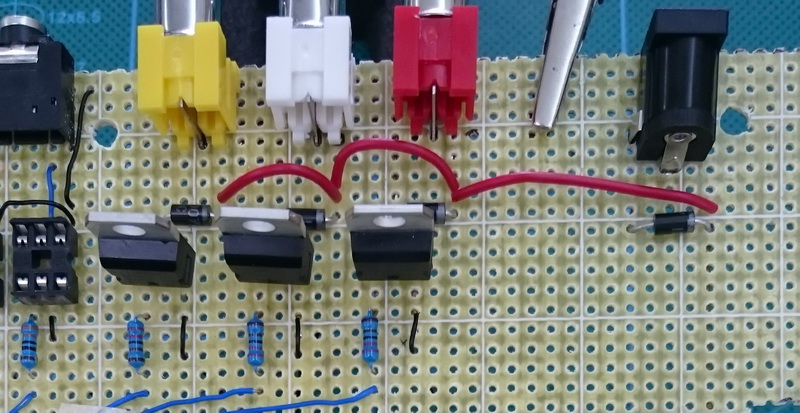
The 12V wires connect to the RCA socket and the 1N4007 diode.

Step Down Power Converter
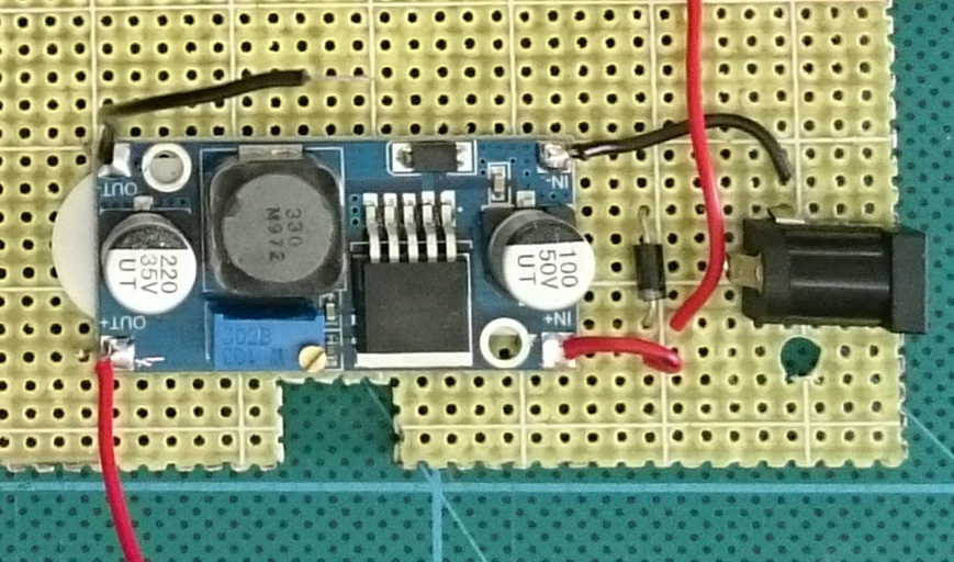
I am using a pre-made DC-DC step down power converter which I attached to the perf board with a double side sticky foam tab. For the step down converter you can also use a 7805 or 7806.

Place the power converter and solder the voltage in and GND wires. The GND wire goes directly to the socket, the VCC wire goes to the diode.
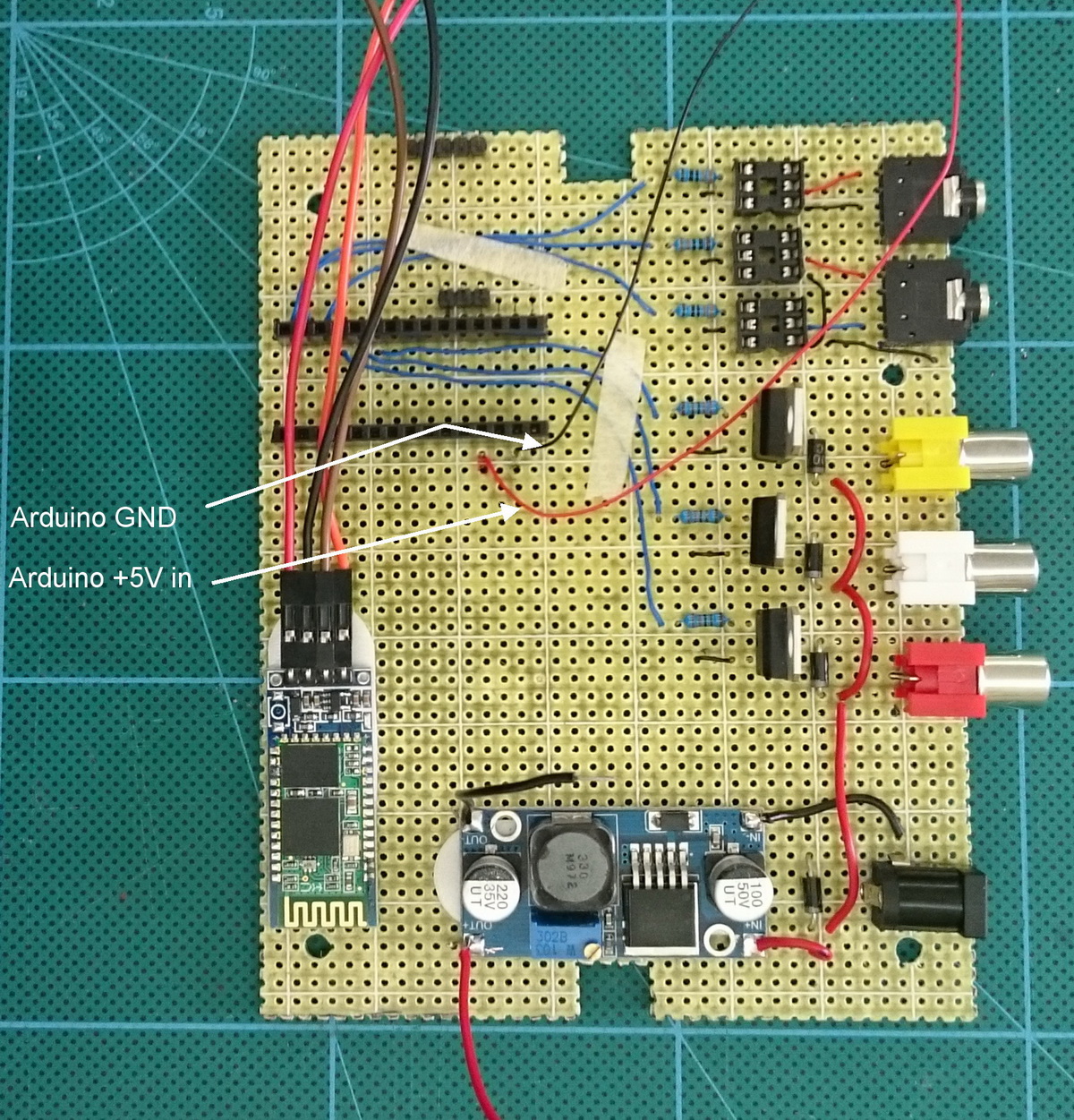
Add the Bluetooth module (I used sticky foam pads to attached this as well).
Add VCC (+5V in) and GND wires to the Arduino
The DC-DC step down converter has a small pot that is used to change the value of the output voltage.
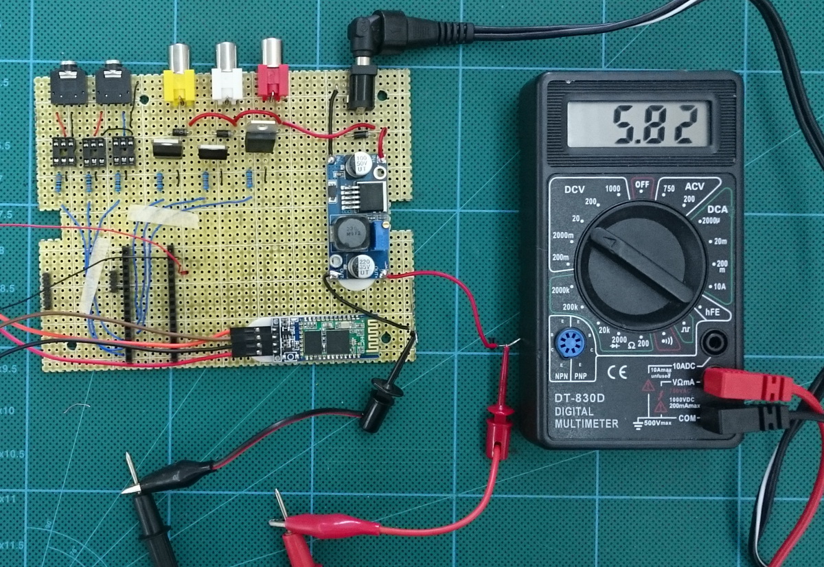
I set this to about 5.7/5.8 volts. The 1N4007 diode on the voltage out has a forward drop of 0.7 volts. So the 5.7V will become 5Vs after the diode. The Atmega chip can handle up to around 5.3V without any problems so slightly more than 5V is OK. The HC-06 can handle up to 6V.
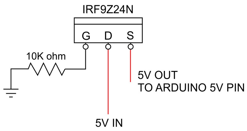
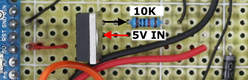
Add the mosfet
When I was developing the dropController, I had a weird problem, when the Arduino was connected to a computer by usb and at the same time the device was powered by the external power supply, the computer would crash when the usb cable was unplugged (it was fine until I unplugged it). I fixed this by adding a diode to the 5V out line on the Arduino. This stopped the computer crashing but unfortunately the diode ate too much power (fairly high forward voltage drop). Later I changed the diode to a mosfet. The mosfet offers the same polarity protection without the large forward voltage drop.
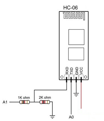
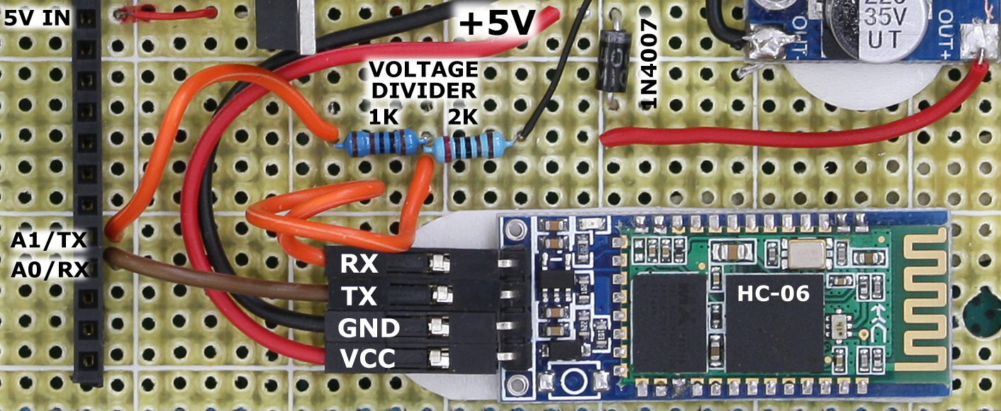
Connect the HC-06
The small daughter board on the HC-05s and HC-06s are 3.3V devices. Most of the cheap HC-06s and HC-05s have an on board voltage regulator that reduces an input power (up to 6V) to the required 3.3V. The RX and TX pins are still 3.3V though. A 5V Arduino reads 3.3V as HIGH so the BT module TX pin can be connected directly to the Arduino RX pin. The BT module RX pin cannot be connected directly and the voltage needs to be brought down to 3.3V. A simple way to do this is by using a voltage divider. I normally use 1K ohm and 2K ohm resistors.
As a quick guide to the voltage divider; 1K + 2K = 3K. 1K is a third of 3K so it reduces the voltage by a third. One third of 5V is 1.66 and 5-1.66 = 3.33 which is what we want. Putting the resistors the other way would reduce the voltage by 2 thirds. For more information on voltage dividers have a look at the Sparkfun tutorial
Double check the resistors you are using. It is very easy to use the wrong values.
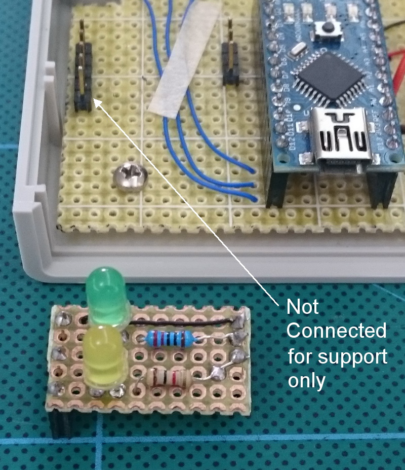
Status LEDs
Initially I wanted to mount the LEDs on the case but I couldn’t find any LED clips locally and due to the cost of postage I didn’t want to order from the internet so I made a small daughter board. The small board raises the LEDs so that, once I have drilled holes, they can be seen through the case.
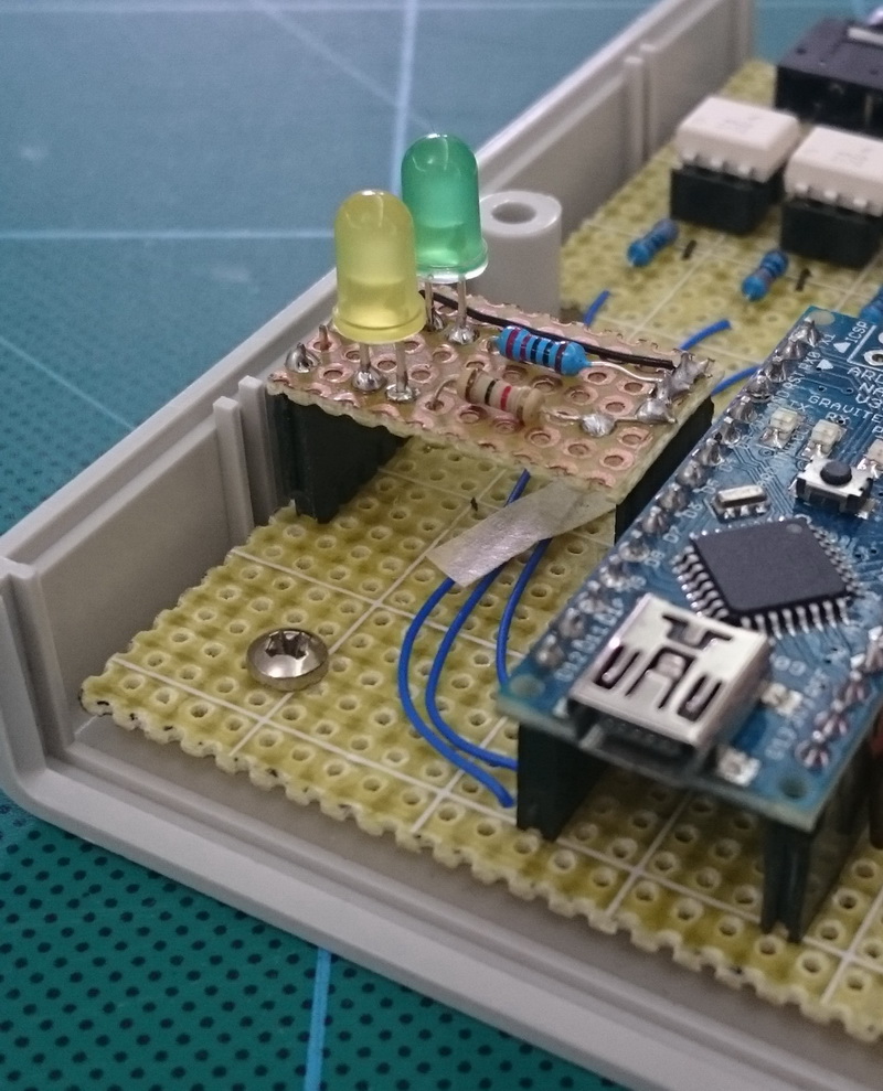
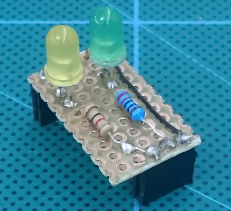
The yellow LED is much brighter then the green one so I used a larger resistor to reduce the brightness.
Join the GND wires together
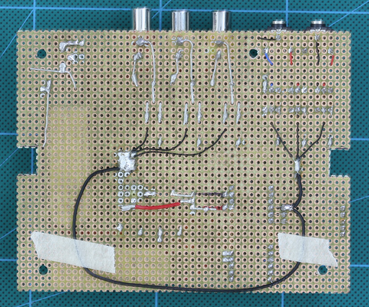
Final Board

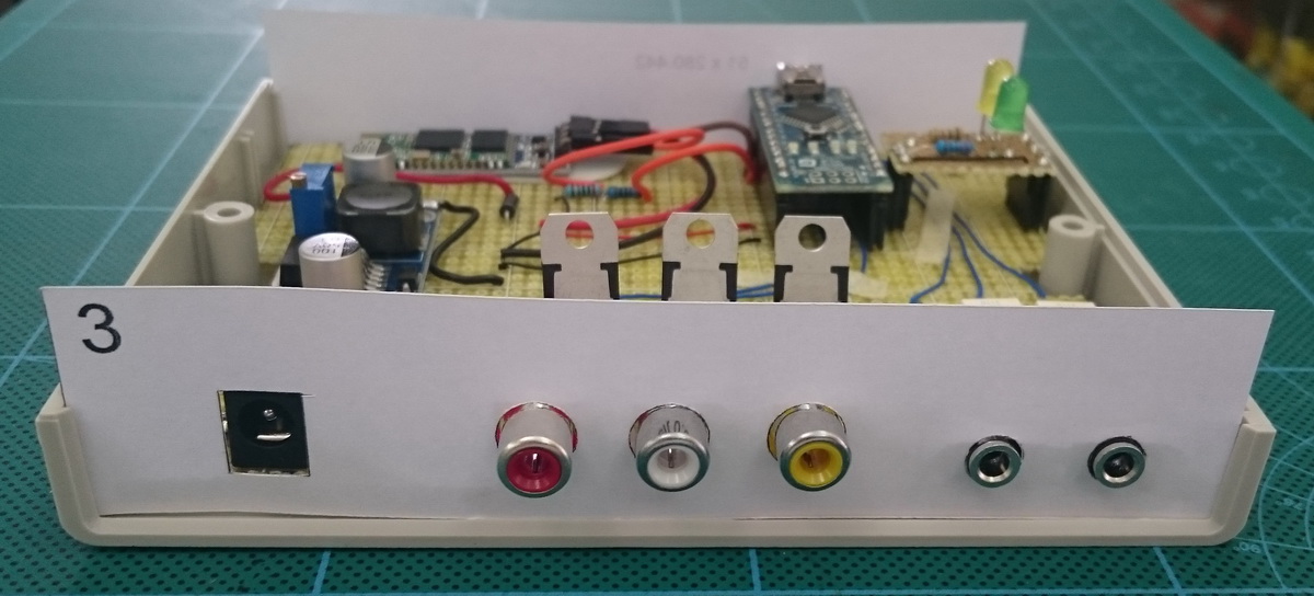
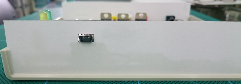
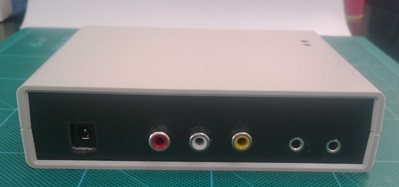
Back and front plates
Once I had the curcuit completed I measure where all the connectors were and created templates for the holes.
And here is the finished dropControllerBT
awesome work Martin.
I am very new to all this circuit and electronics.
I am trying to build this, and following your guide.
I am not able to get the program for arduino. Can you please provide the same which you have used? Or the link of the guide for using the same.
Regards,
Shantanu
The Arduino sketch and the Android app can be downloaded on the main dropcontrollerBT page.
https://www.dropcontroller.com/dropcontrollerbt/
See the download links at the bottom of the page.
Hi
Just a note to say thanks for the very clear information and also to ask a question.
I have been told that if you want to use multiple flash guns then it’s hard to get them to all fire together from one gun or a trigger, particularly if they are on low power to get the fastest flash.
Do you think it is possible to add more flash outputs from the unit as this is I am told the best way to ensure good results
The easiest way is to use a cable splitter such as the headphone splitters used for audio. See https://www.dropcontroller.com/cables-and-leads/. These can be stacked as many times as you wish.
You could also build a flash distributor. I built one that has one signal in and 4 out. The only restriction is that all the flashes need to be the same voltage.
If you want to create additional sockets on the dropController have a look at https://www.dropcontroller.com/forums/topic/use-of-more-flashes/.
I now use radio controlled flashes which are a lot more convenient.
I am now starting to build a version 3 of the dropController. This will have extra triggers but I have no idea when it will be ready.
Hi Martyn
firstly thanks for sharing your dropcontroller. I’m currently building the dropcontroller BT still waiting for a few parts too arrive from China. I’m a hobby photographer and a commercial dropcontroller would be too expensive for my budget. So thanks again.
I have a suggestion. would it be possible to update the app to use the androids own Mic as a trigger, adding sound. Instead of triggering the drops simply triggering the camera and flash. We all know how useful that could be. ” Breaking glass, ballistics. Ect” ?
Thanks Ralph.
While possible to use the phones mic the delay between the sound and the flash trigger would be too great.
The very first dropController was part of a camera control device I have. As it developed it became cumbersome and so I separated the dropController part. I keep thinking about publishing the control device but (as with a lot of things) I never get round to starting.
If you want to have a try at this kind of photography, take a look at the multifunction camera triggers like the Photoduino (http://photoduino.com/), the High Speed Photo Trigger (http://mrossphoto.com/high-speed-trigger/) and early versions of the cameraxe (http://www.cameraxe.com/).
Also look at the circuits on the HiViz website, especially the assembly instruction section