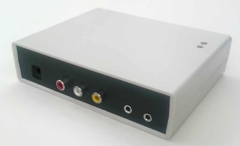
If you are building your own device please build version 3.
dropController version 2 started as a simple 3 valve controller controlled by a host computer over USB. I later added Bluetooth and an Android app and finally added 3 more valves. Due to how the device developed certain parts were a compromise. For example, the pins used for the solenoid valves.
Rather than continuing to patch version 2 I moved to version 3 and redesigned the controller from scratch. Although I no longer develop Version 2 is still in use by many people so I still correct bugs when they are found.
I created new apps for version 3 which I have made backward compatible with the version 2 device and so I now only support 1 Android app and 1 Windows app. Previously V2 and V3 had separate apps.
Breadboard version of a 3 valve dropController V2
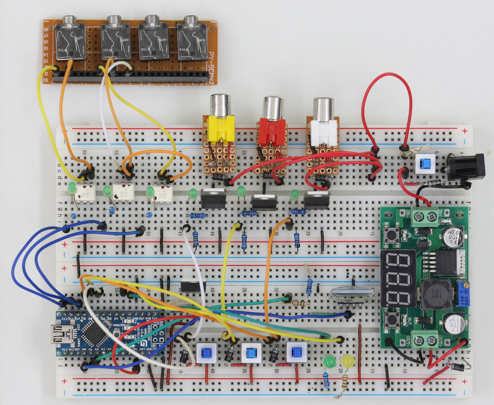
You may notice that the breadboard version has LEDs, to show when the camera and the solenoids are active, and switches for draining the valves. These are not required and do not feature in the circuit diagram.
Perf Board Version of a 3 valve dropController V2
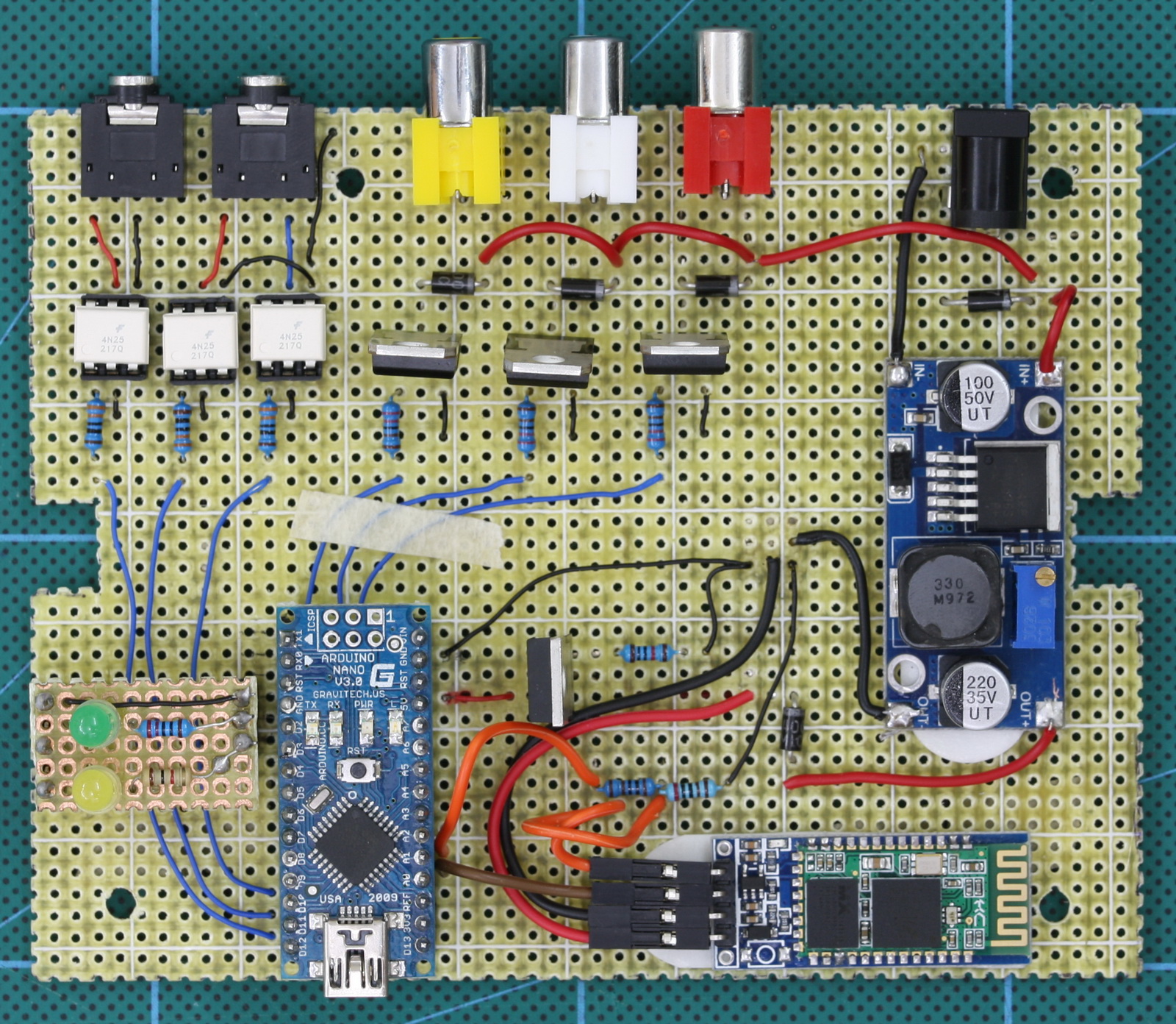
Since the perf board version is intended to go inside a box there no activity LEDs. I also removed the valve drain switches. Draining the valves is done through the app so no physical switches.
Build Guides
Build guide for the 3 valve breadboard version.
Build guide for the 3 valve perf board version.
not traditional electronic build guides but enough information and photos to enable just about anybody to build a dropController.
Please note the guides are for a 3 valve version. After the guides were created 3 more valves were added to pins D4, D5, and D6.
D4 – valve number 4.
D5 – valve number 5.
D6 – valve number 6.
Here is the circuit for a 6 valve version.
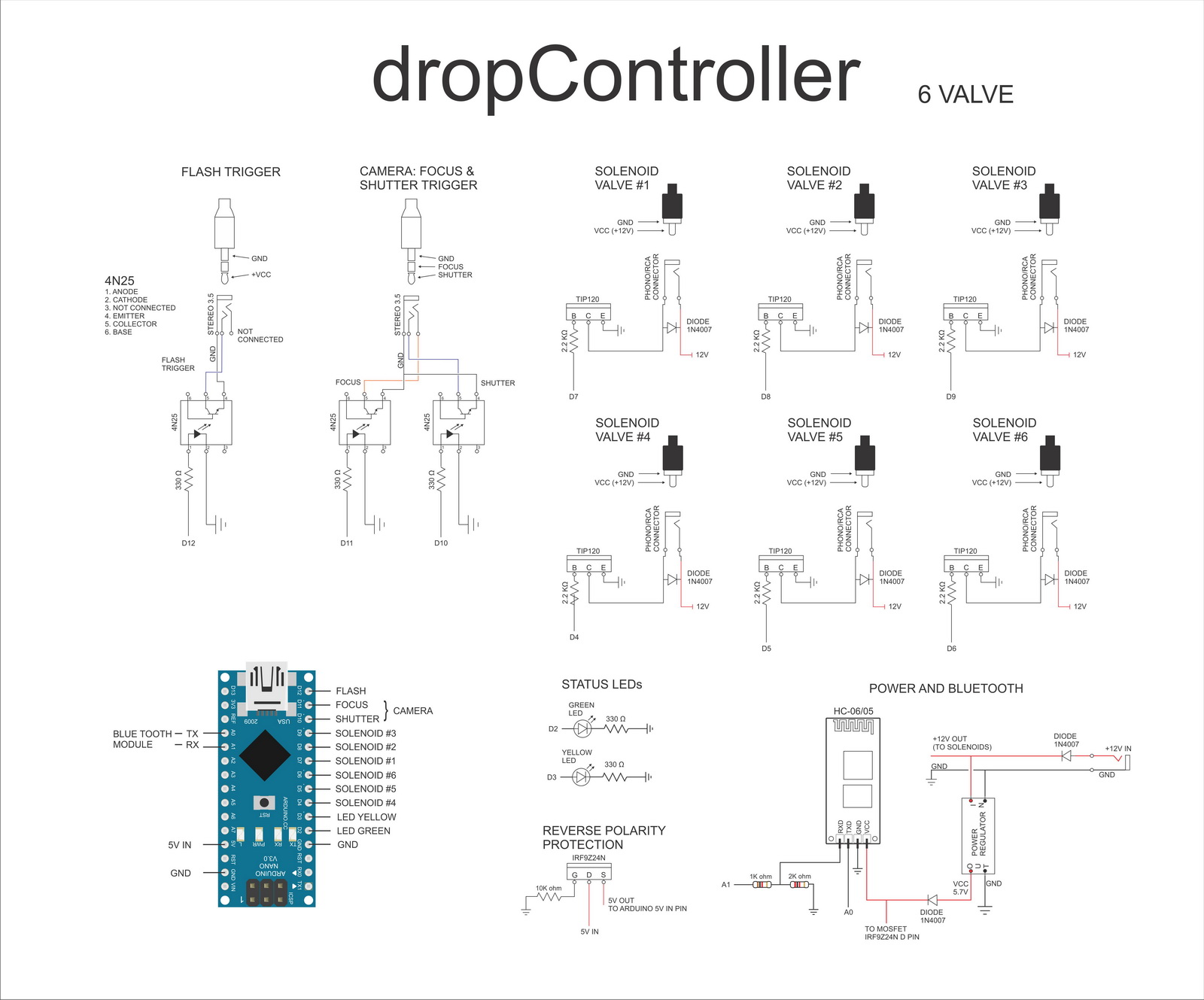
I was never happy about the pins used for the extra solenoid valves but wanted to keep the original pins for consistency. The pins can be moved if desired. The pins are defined in the sketch starting at line 140. and only these lines need to be changed to move the pins around.
const byte LED_ACTIVE_PIN        = 3;
const byte LED_WAITING_PIN       = 2;

const byte CT_SHUTTER_PIN        = 10;
const byte CT_FOCUS_PIN          = 11;

const byte FT1_PIN               = 12;

const byte ST1_PIN               = 7;
const byte ST2_PIN               = 8;
const byte ST3_PIN               = 9;
const byte ST4_PIN               = 4;
const byte ST5_PIN               = 5;
const byte ST6_PIN               = 6;
CT = Camera Trigger
FT = Flash Trigger
ST – Solenoid Trigger
Arduino Sketch
The dropController uses a regular 5V Arduino Nano and the code (or sketch) was created using Arduino IDE V1.8.5. The sketch can be downloaded from the Download page. Double check that you are downloading the sketch for version 2.
Android App
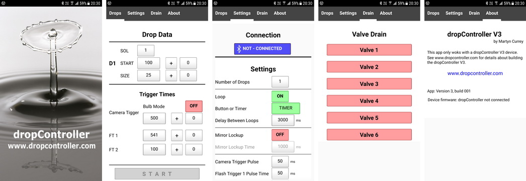
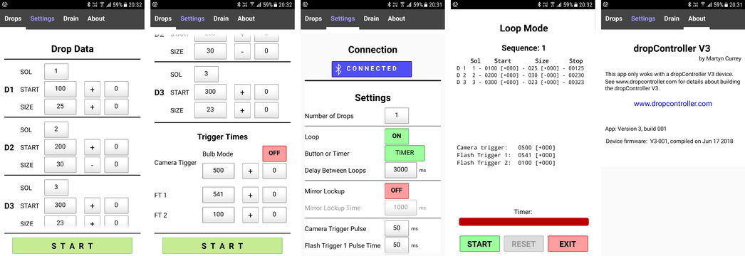
dropController version 2 and version 3 use the same app. Select the version of the device you are using on the About tab:
![]()
Windows App
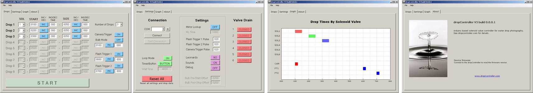
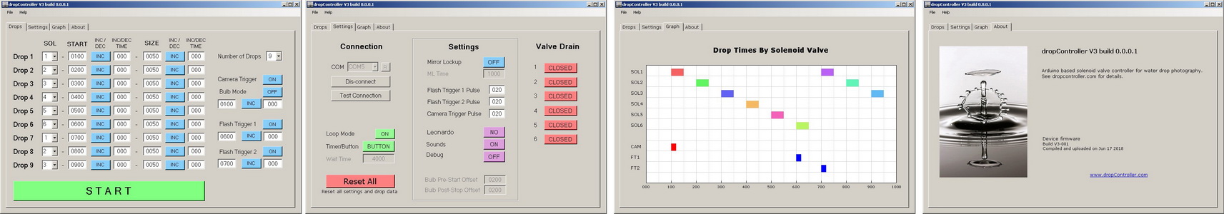
dropController version 2 and version 3 now use the same app. Select the version of the device you are using on the Settings tab:

Setting up a Bluetooth HC-06 module
I have a mini guide that explains how to set up the Bluetooth module.