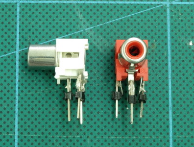
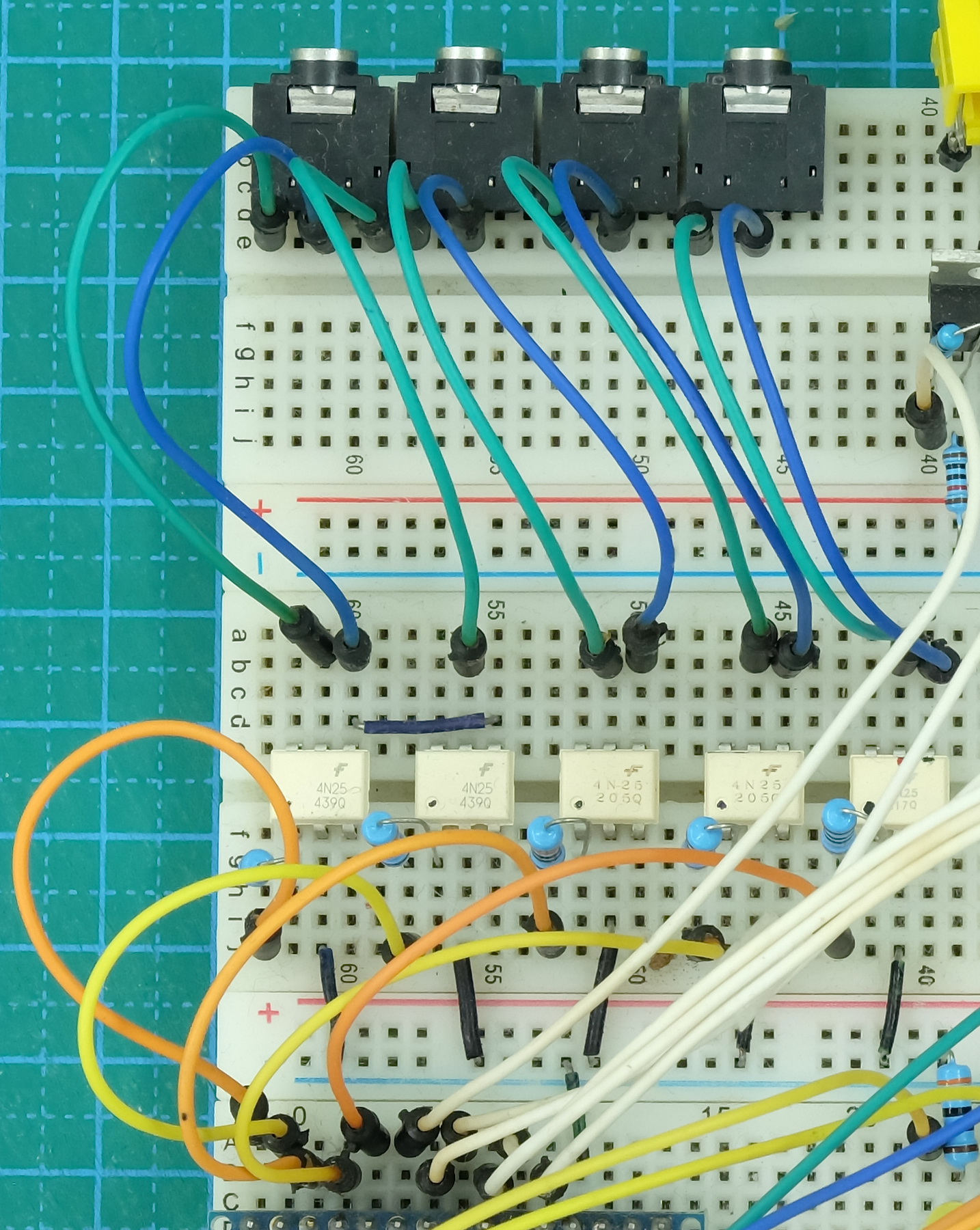
Anybody who is in any way familiar with the Arduino or similar development boards should be able to build a dropController on a breadboard. The only difficult part may be the RCA and 3.5mm connectors which are unlikely to be breadboard friendly. To the RCA sockets, for example, I soldered pins to the feet so they would fit in to the breadboard holes.
I built the prototype using 3 breadboards to give myself plenty of space. With a bit of work you could reduce it to 2 boards.
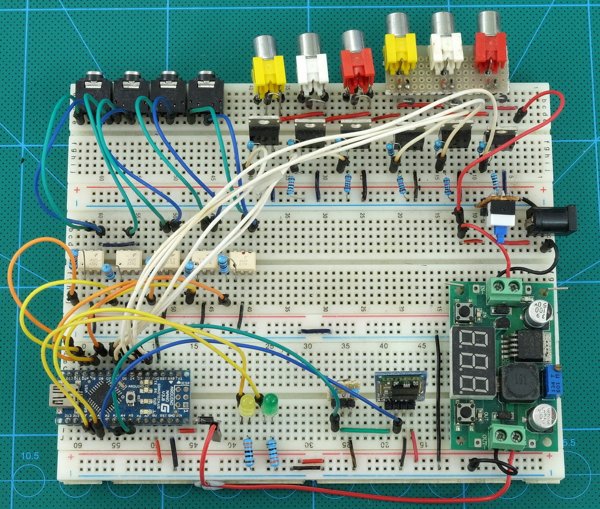
Although I call this a prototype I used a breadboard version for a quite a while before building a protoboard version.
Unfortunately I do not have a step-by-step guide to building the breadboard version. I hope to add this is the future, in the meantime I hope the photos below and the circuit diagram are enough to enable people to put the circuit together.
Parts List
Breadboards
Jumper wires
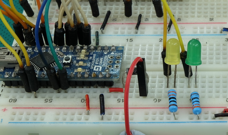
1 x Arduino Nano V3
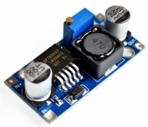
1 x LM2596s Buck converter. DC to DC step down power supply
1 x HC-06 Bluetooth module
1 x Yellow LED
1 x Green LED
1 x Barrel jack/power socket
6 x RCA/phone socket – RCA-RCJ-04x / Terminal contacts
4 x 3.5mm stereo socket – PJ-307 3.5mm stereo connector
5 x 4N35 (or similar) optocoupler
6 x IRL540N mosfet (or similar)
7 x 1N4007 diode
7 x 330 Ohm resister
6 x 220 Ohm resister
6 x 10K Ohm resister
1 x 1K Ohm resistor
1 x 2K Ohm resister
For details about the mosfets and optocouplers (4N25s) see the Circuit page.
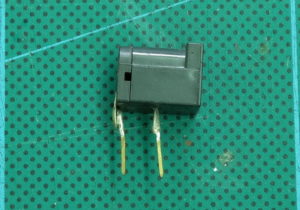
RCA sockets and power barrel jack socket
The RCA sockets and power barrel jack socket I used are not breadboard friendly For the first few RCA sockets I added pins and then for the other 3 I built a small prototype module that plugs in to the breadboard.
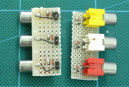
I personally feel, if you are going to take the time to build small breadboard friendly boards you might as well build a protoboard version. I made the ones above because I do a lot of breadboarding and I use them in other circuits.
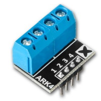
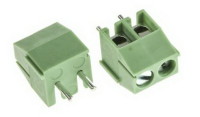
Terminal blocks/connectors make a good alternative to the phono RCA sockets. If you are using a breadboard make sure you get the correct size. Breadboards are 0.1″ / .25mm spacing.
</p >
Power
The dropController V3 can use either 12V or 24V power. This allows you to use either 12V or 24V valves. Take care to match the valve with the voltage you are using and do not mix different voltage valves. I used to use multi-voltage power supplies but these proved to be unreliable and when the last one died I settled on a 24V fixed voltage supply. At the same time I changed the coils on my favourite 12v valves to make them 24v.
LM2596s Buck converter
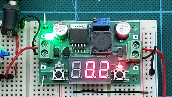
For the breadboard prototype I used a DC-DC converter with a display that shows the output voltage. This allows me to set the voltage without the need of a multimeter (or Arduino voltmeter). When using a variable voltage out buck set the output to around 8V before connecting to the main circuit. The voltage regulator on the Arduino can safely accept voltages from 7-12V so it is not critical to get exactly 8V.
I use a smaller buck converter in the kits; either a variable converter or a fixed 9V one. The fixed output version is easier to work with.

</p >
The fixed output converters are available with various output voltages preset so make sure you buy the right one.
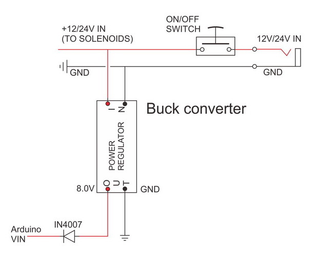
Power is directly connected to the valves and also a DC-DC step down buck converter that is set to step down the input voltage to 8V. The 8V is then connected to a 1N4007 diode and then to the Arduino VIN pin. The diode adds reverse voltage protection for when the Arduino is connected to a USB power supply (like a computer) and also powered from an separate power adapter). The Arduino VIN pin is connected to the Arduino on board voltage regulator which converts the voltage to 5V.

The voltage regulator on the Arduino can safely accept voltages from 7-12V so it is not critical to get exactly 8V out from the buck converter. The 1N4008 diode has a 0.7/0.8 voltage drop. This means although there is 8V coming from the buck converter the diode uses 0.8 volts and so passes 7.2V to the Arduino. This is around as low as you should go to ensure the MCU on the Arduino gets 5V.
Remember to set the out voltage before connecting to the circuit.
If you do not have a multimeter you can use an Arduino. See Arduino voltmeter.
LEDs
- D14/A0: Yellow LED
- D15/A1: Green LED
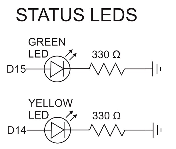
The 2 LEDs show the device status:
- The yellow LED shows the connected status; slow blink means not connected. Solid on means connected to an app.
- The green LED shows when the device is active (making drops).
When drops are being produced the yellow LED turns off and the green LED turns on. When the drop sequence is finished they go back to Yellow on, green off.
If both LEDs flash together rapidly it means there is an error in the drop data. This is just for debugging purposes.
The circuit shows 330 ohm resistors and with 330 ohm the LEDS are quite bright. To make the LEDs less bright you can use larger value resistors.
Camera and flash triggers
Optocouplers are used as digital switches to trigger the camera and flash guns. To help keep the circuit as simply as possible I use separate optocouplers. I also use stereo sockets throughout.
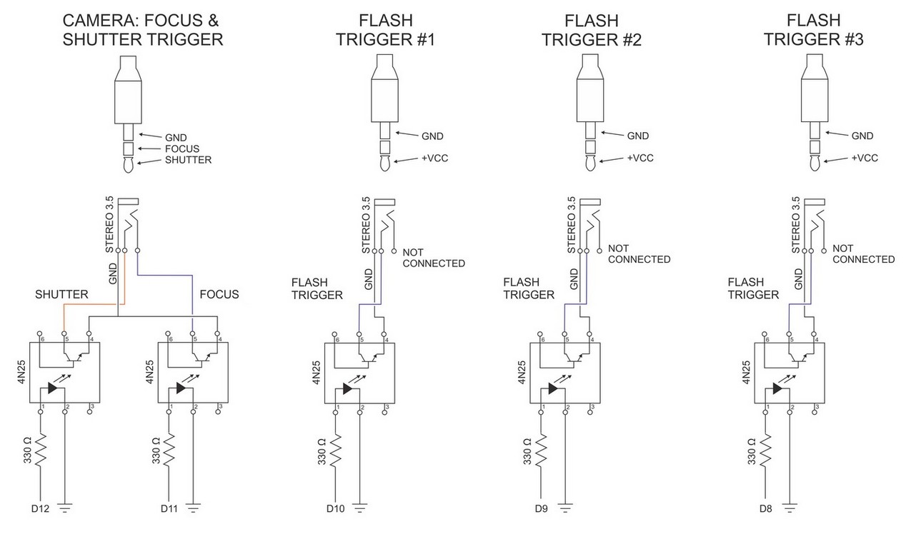
Shutter and focus triggers always fire together and is required by some cameras to trigger bulb mode. For example, on my Canon 40D, Bulb mode does not start when triggering the shutter only.
Optocoupler
The circuit shows 4N25s (these are very common and very cheap) and similar chips (such s 4N26s) can be used. An optocoupler isolates one circuit from another. Using the 4N35 means the circuit on the dropController side is not electrically connected to the camera circuit and offers the camera a fair amount of protection. It is not 100% fool proof though, check the data sheets for the optocoupler you use for full details.
Connect the camera and flashes to the optocouplers only. The GNDs are not common so do not connect the camera and flash GNDs to the main circuit.
Solenoid valve triggers
The valves use a higher voltage than the camera and flashes and optocouplers like the 4N35 are not suitable, instead, mosfets are used. Like the optocouplers the mosfets are used as digital switches.
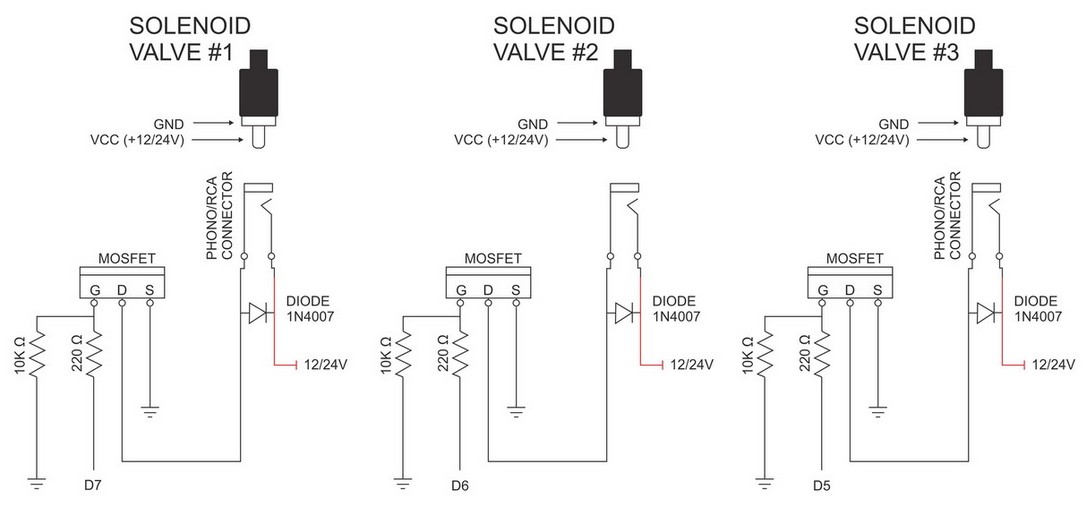
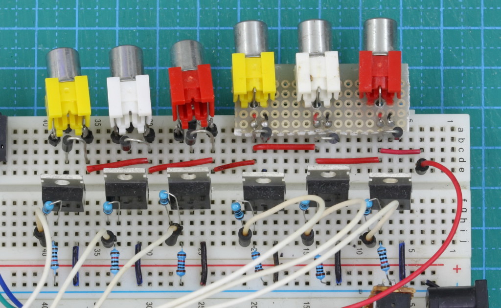
Mosfets
To switch the solenoid valves I am using IRL540N mosfets and any similar logic level mosfet can be used. You need a 5V logic level mosfet with a low RDS(on) value at 5v (ideally 4.5v or lower). The IRLZ44N is also suitable. I have a list I can publish if anybody wants it.
Flyback Diode
A solenoid is a electromagnet device and works by using a magnetic force to move a small piston (they are inductive). When the current is removed the magnetic fields collapses and the piston moves back. When the magnetic field collapses it also generates a voltage. This can be very high and if allowed to feed back to the main circuit could cause damage. To stop the feed back a flyback diode is used. The diode directs the current back to the solenoid until it dissipates.
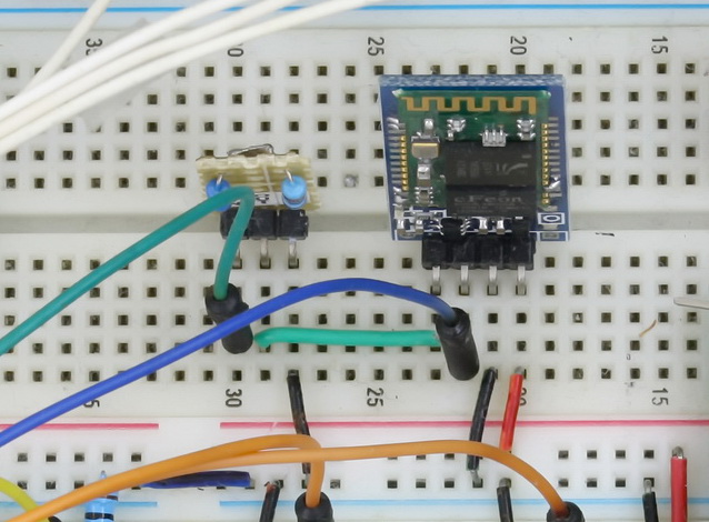
Bluetooth Module
Either a HC-06 or HC-05 (in slave mode) can be used but I recommend the HC-06 because it it easier to set up. I also recommend getting the official HC-06 from hc-01/Waven. These have HC01 screen printed on the board and have an extra blue LED at top left. The module in the photos is not an official HC-06 though.
The Bluetooth module connects to the Arduino using software serial on pins A4 & A5 which are used as digital pins (D18 & D19). Power is delivered from the Arduino 5V pin.