This is very out-of-date and I am now on version 3 of the dropController. I also moved away from keypad control. Left this page online due to the interest in the menu system I created and although it is integrated in to the code it should not be too difficult to adapt.
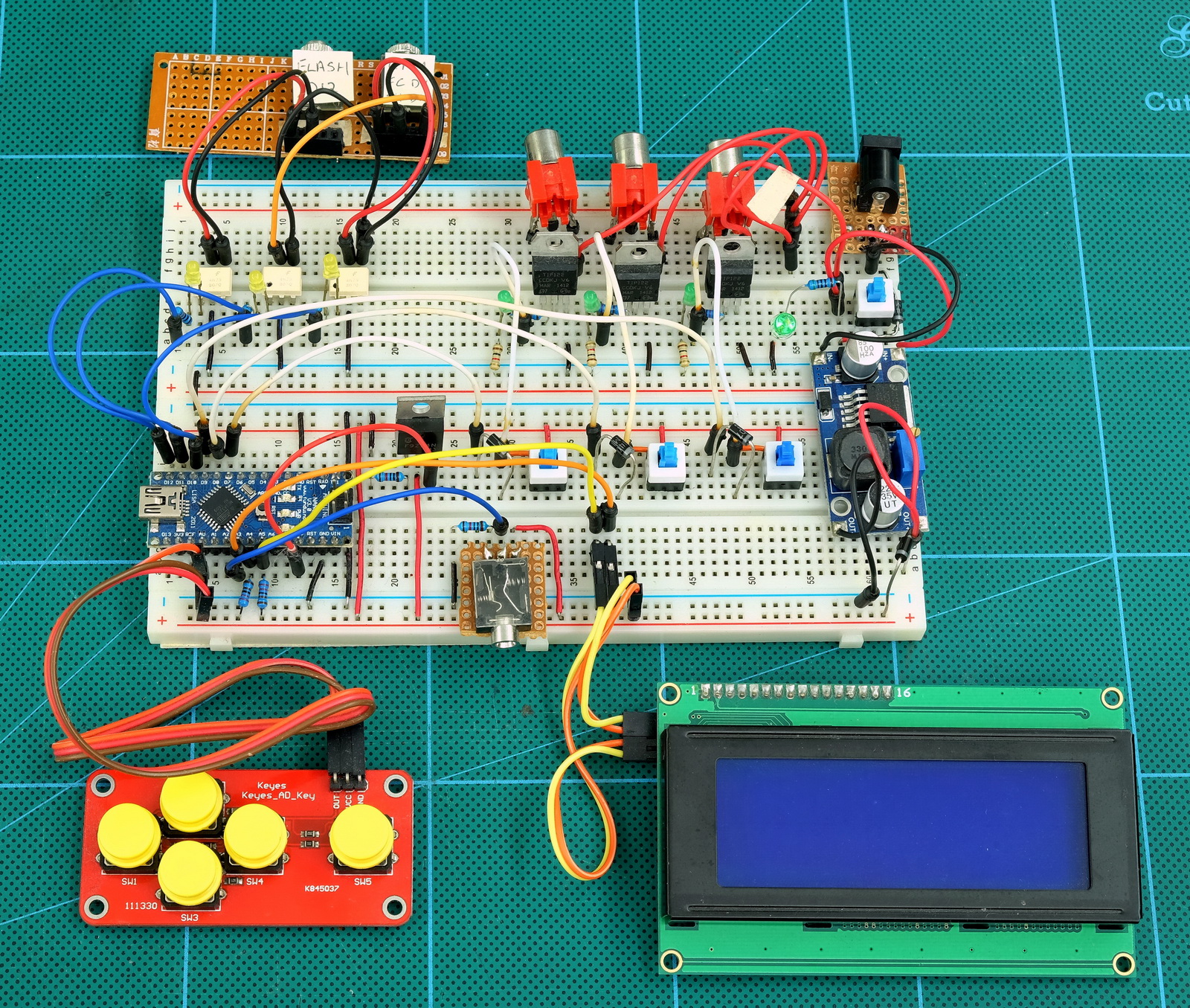
The circuit is fairly simply and should be able to be created by anybody.
Arduino pins
The dropController uses the following pins
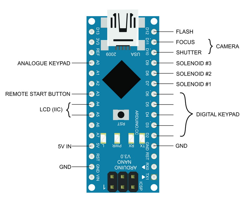
Connections for 2 types of keypad are shown but only one type would actually be used.
Parts List
Bread Board x 2
Arduino Nano x 1 (or similar)
DC-DC step down power regulator x 1 (or some other power regulator)
20×4 LCD with IIC back board x 1
Navigation Keypad x 1
Push button switch on lead x 1 (remote start button)
4N25 optocoupler x 3 (or similar)
TIP120 x 3 (or similar. I used TIP122s)
On/off switches x 4
3.5 stereo socket x 3 (camera and flash connections + remote switch connector)
RCA/Phono socket x 3 (solenoid connections)
1N4007 diode x 8
330 ohm resistor x 3 (optocouplers)
470 ohm 1/2W (power on LED)
1K ohm resistor x 3 (LEDs on the TIP120s)
2.2k ohm resistor x 5 (2 for the LCD, 3 for the TIP120s)
10K ohm resistor x 1 (remote button switch)
IRF9Z24N Mosfet x 1 (or similar)
LEDs x 7
Circuit Diagram
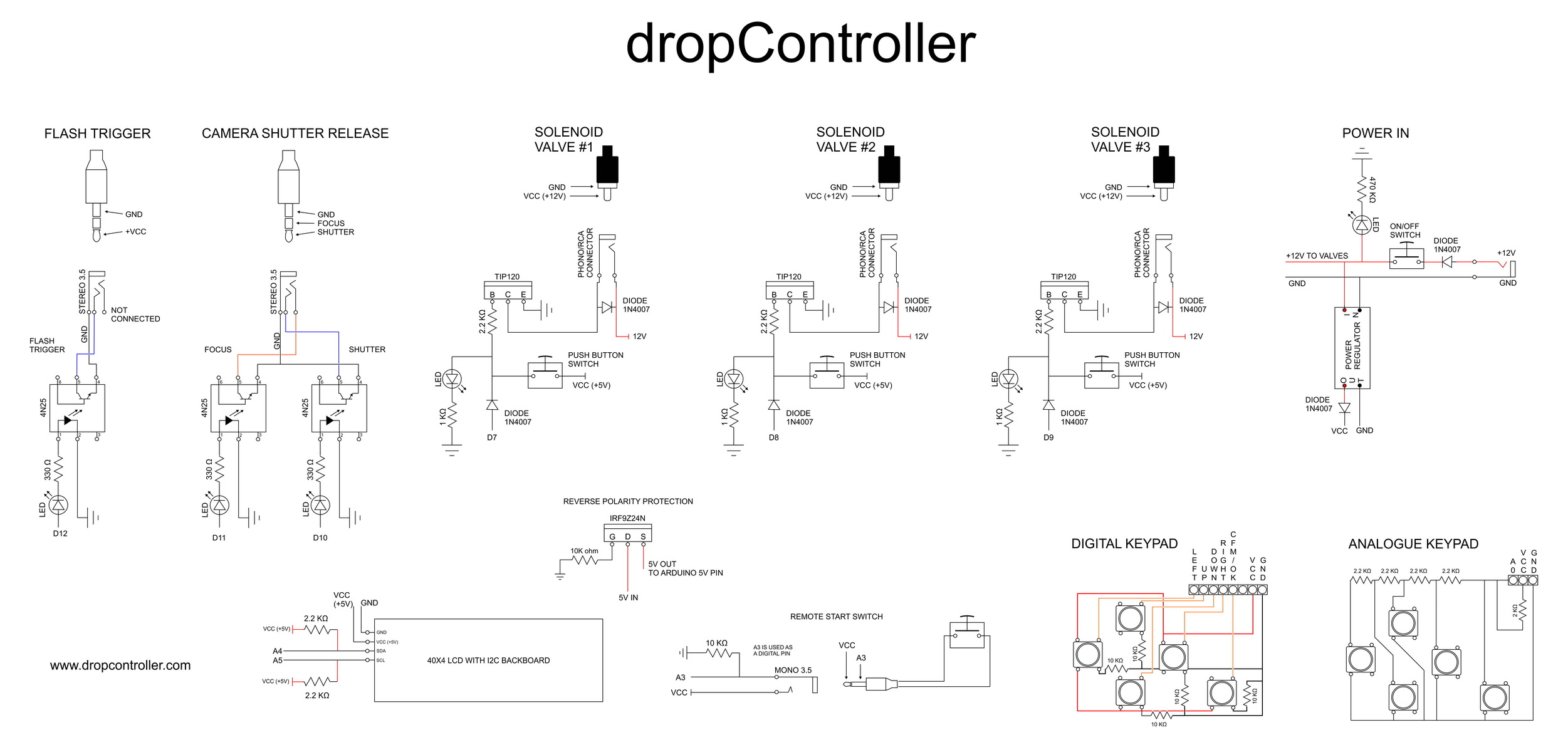
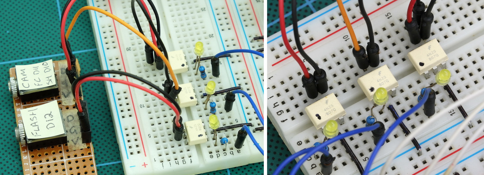
Camera and flash triggers
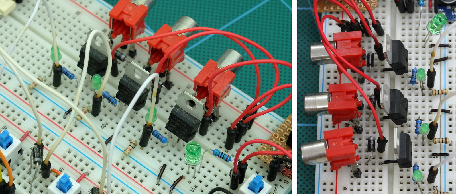
The camera trigger circuit uses 4N25/26 opto-couplers as digital switches (I have used both 25’s and 26’s since these were what I had but other models can be used). Opto-couplers allow the Arduino to trigger the camera and flashes without having a direct electrical connection. More info here. The camera focus and camera shutter triggers use separate opto-couplers which then go to the same 3.5 connector. I have a Canon camera which requires both focus and shutter to be active for bulb mode to work.
Solenoid valve connections
The solenoid valves are controlled through TIP120’s. These are used as digital switches similar to the opto-couplers. The difference is the TIP120’s allow a larger voltage/current to be switched.
Power supply
The dropController and the solenoid valves are powered from the same 12V wall wart power supply. The 12V goes directly to the solenoid valves and also to a step down converter. The converter steps down the voltage to 5V which goes to the Arduino.
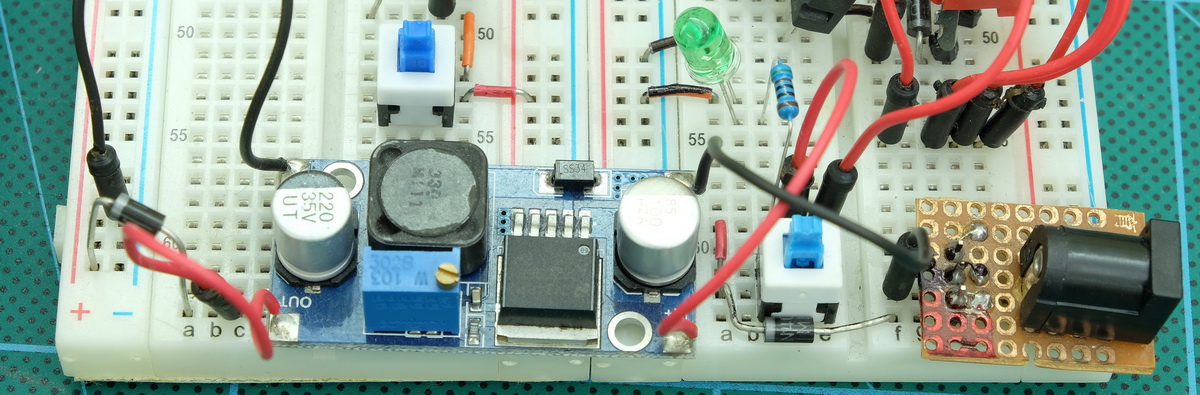
Different DC converters can be used, for example a LM7805/06. The circuit I use is taken from Derek Molloy’s video at https://www.youtube.com/watch?v=FVMrA8C-GM0
I use an LM7806 with an in line diode on the output pin. The LM706 reduces the voltage to 6V and the diode further reduces it to 5.3V. 5.3V is an acceptable input voltage (just) for the Arduino’s 5V pin..
In an earlier version of the dropCopntroller I had a weird problem. When the Arduino was connected to a computer by usb and at the same time the device was powered by the external power supply, the computer would crash (BSOD) when the usb cable was unpluged. Everything worked fine while things were plugged in it was only when the usb cable was pulled out I had a problem. I initially fixed this by using a diode but the diode had a fairly high voltage drop. I later replaced the diode with a mosfet. The mosfet offers the same polarity protection without the large forward voltage drop.
When there is power on the 5V line in to the mosfet the mosfet is turned on and allows current to flow. Remove the 5V and the mosfet turns off. This means, when the Arduino is plugged in to a computer and at the same time the external power supply is connected, the Arduino will use the usb power and the mosfet will stop the current going to the rest of the circuit which is powered by the external power supply.

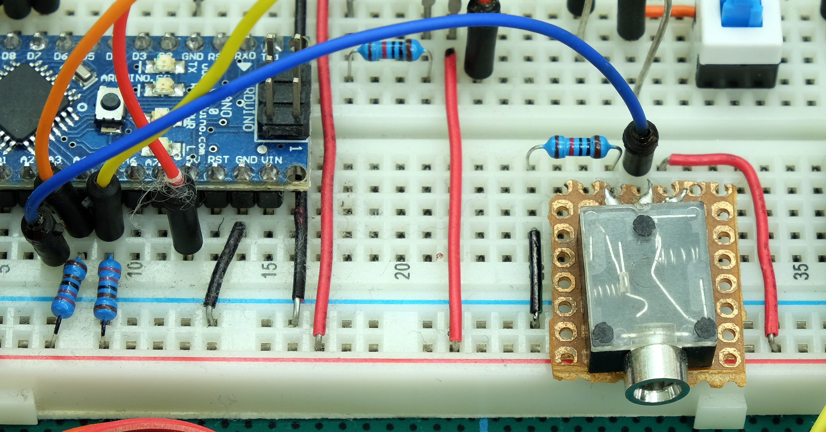
Remote start button switch
The remote button switch is exactly the same as the switches used for the digital keypad. The only difference is it is on the end of a cord and connected by a 3.5 jack. The A3 pin is used as a digital input pin for the switch.
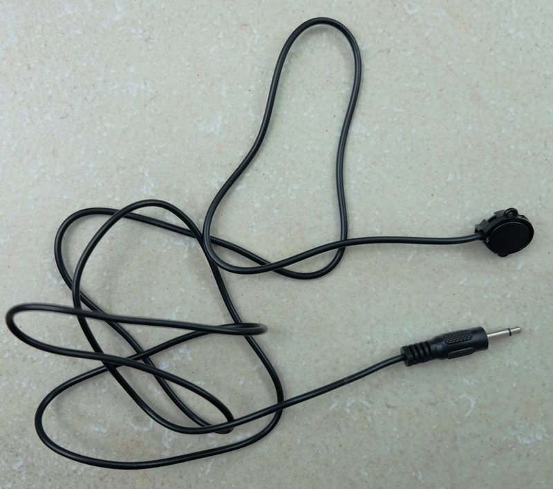
Here is my remote cable.
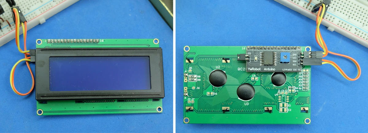
LCD screen
The LCD is a regular 4×20 character display with an I2C daughter board. Using I2C means the display only uses 2 pins on the Arduino; A4 and A5.
Navigation keypad
The dropController can now use either a digital keypad or an analogue keypad. When I first started I could not find suitable navigation keypads so I built my own. Later, I found pre-made analogue keypads. It is fairly straight forward to make your own keypads, either digital or analogue, see here for details.
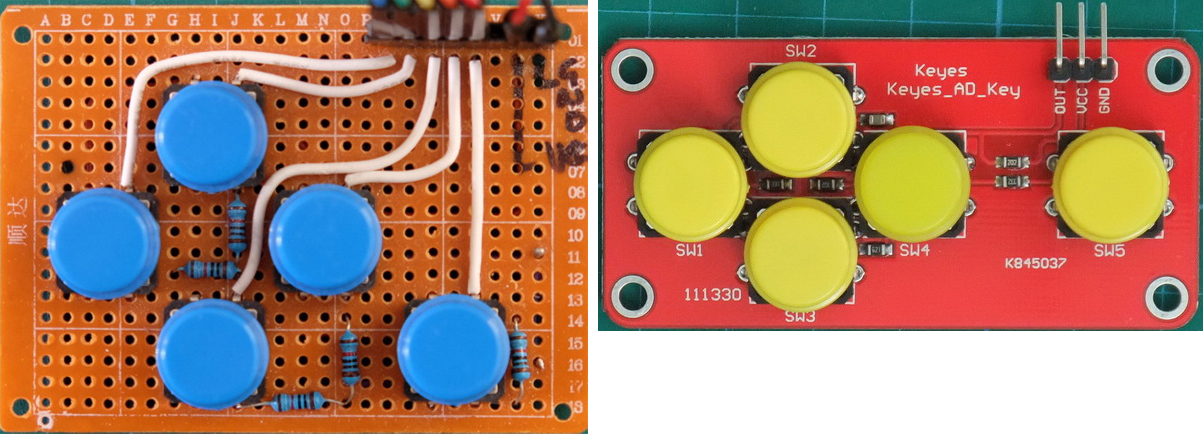
The Arduino sketch defaults to the analogue keypad. To change to the digital keypad you need to edit the sketch. I recommend using an analogue keypad and if I ever update the dropController I will remove the digital keypad option.
As downloaded the sketch is set to use the analogue keypad
// comment out the type of keypad you are not using
#define KEYPAD_ANALOGUE
//#define KEYPAD_DIGITAL
to change to a digital keypad, uncomment #define KEYPAD_DIGITAL and comment out #define KEYPAD_ANALOGUE
// comment out the type of keypad you are not using
//#define KEYPAD_ANALOGUE
#define KEYPAD_DIGITAL
The Arduino IDE will automatically select the correct code to compile.
The key switch values for the analogue keypads are not standard. I have several of the Keyes boards and they all return different values. The boards I have made myself also return different values. Therefore, if using an analogue keypad you may need to change the values for each button and edit the sketch “dropController_3_01” at line 214 onwards:
// uncomment the type of keypad you are using
#define KEYPAD_ANALOGUE
//#define KEYPAD_DIGITAL

const int VAL_LEFT_MIN = 0;
const int VAL_LEFT_MAX = 100;
const int VAL_UP_MIN = 150;
const int VAL_UP_MAX = 250;
const int VAL_DOWN_MIN = 325;
const int VAL_DOWN_MAX = 425;
const int VAL_RIGHT_MIN = 480;
const int VAL_RIGHT_MAX = 580;
const int VAL_SELECT_MIN = 700;
const int VAL_SELECT_MAX = 800;
const int VAL_NO_KEY_MIN  = 900;
const int VAL_NO_KEY_MAX  = 1024;
Each button switch has a minimum and a maximum value. I have set these to the button value -50 and the button value +50. For example. LEFT = 50, so I have set LEFT_MIN to 0 and LEFT_MAX to 100.
At some point I plan to add a calibrate function to the sketch so that manually editing will no longer be required.
Downloads
dropController Manual (draft version)
Arduino sketch Version 3.01
The Arduino sketch is an ino file and you will need to use the Arduino IDE to compile it and then upload it to an Arduino
The sketch has 7 tabs:
– dropControl
– Functions
– Create_Menu_strings
– Eeprom
– Menu
– Make_Drops
– Keypad
The main sketch is in the dropControl tab.
The dropController sketch uses the following Arduino libraries:
– EEPROM. Included in the Arduino installation
– Wire. Included in the Arduino installation
– Button. Download from here
– digital IO performance. Download from here
– LiquidCrystal_I2C. I used the version from here. The LCD page on the Arduino Wiki is very helpful.
– MemoryFree. Available from GitHub.
Libraries must be installed in the correct Arduino folder before they can used. For more information have a look here and here.
To Do
Calibrate analogue keypads. At present you have to manually enter the values for the analogue keypad. I plan to add a function to allow calibration from within the sketch.
Remove the memory banks. At present you can save 3 sets of drop data. I now feel this is not required and 1 set is enough. This means I can remove the load & save functions and menu options. At the same time I will probably rewrite the save to eeprom function.