Version 2 of the dropController is still breadboard only at this time. I plan to build a more permanent version in the near future after I have completed the blue tooth version.
The circuit is fairly simply and should be able to be created by anybody.
Arduino pins
The dropController uses the following pins

Connections for 2 types of keypad are shown but only one type would actually be used.
PIN 2 – SELECT
PIN 3 – RIGHT
PIN 4 – DOWN
PIN 5 – UP
PIN 6 – LEFT
PIN 7 – SOL 1
PIN 8 – SOL 2
PIN 9 – SOL 3
PIN 10 – Flash trigger
PIN 11 – Camera trigger – shutter release
PIN 12 – Camera trigger – focus
PIN 13 –
PIN A0 [14] – Analogue keypad
PIN A1 [15] –
PIN A2 [16] –
PIN A3 [17] – Pause/Remote start button (A3 is used as a digital pin)
PIN A4 [18] – LCD
PIN A5 [19] – LCD
PIN A6 [20] –
PIN A7 [21] –
The dropController can use either a digital keypad, where the button switches are connected to separate pins, or an analogue keypad that uses just one pin.
Parts List
Arduino Nano x 1 (or similar)
DC-DC step down power regulator x 1 (or some other power regulator)
20×4 LCD with IIC back board x 1
Navigation Keypad x 1
Single push button switch x 1 (for the remote start button)
4N25 optocoupler x 3 (or similar)
TIP120 x 3 (or similar)
On/off switches x 4
3.5 stereo socket x 3 (camera and flash connections + remote switch connector)
RCA/Phono socket x 3 (solenoid connections)
1N4007 diode x 7
330 ohm resistor x 3
1K ohm resistor x 3
2.2k ohm resistor x 5
10K ohm resistor x 1 (remote button switch)
IRF9Z24N Mosfet x 1 (or similar)
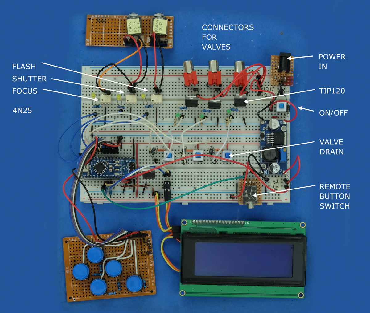
Camera and flash triggers
The camera trigger circuit uses 4N25/26 opto-couplers as digital switches (I have used both 25’s and 26’s since these were what I had but other models can be used). Opto-couplers allow the Arduino to trigger the camera and flashes without having a direct electrical connection. More info here. The camera focus and camera shutter triggers use separate opto-couplers which then go to the same 3.5 connector. I have a Canon camera which requires both focus and shutter to be active for bulb mode to work.

Close up showing the opto-couplers

Solenoid valve connections
The solenoid valves are controlled through TIP120’s. These are used as digital switches similar to the opto-couplers. The difference is the TIP120’s allow a larger voltage/current to be switched.

TIP120’s are used as switches and controlled from the Arduino. The push button switches are to drain the valves. You can also do this in the software but it is not as convenient.
Close up showing the solenoid valve connectors.

Power supply
The dropController and the solenoid valves are powered from the same power supply; either a 12V or a 24V wall wart power supply (I bought them from a local shop). The dropController accepts both voltages but the power supply must be matched to the solenoid values you are using. Valves with different voltages cannot be used together.
When I started working on version 2 of the dropController I only had 12V solenoids and I used a 7806 to reduce the voltage from 12V to 6V to power the Arduino. (see the 12V to 5V/6V post). I later bought 24V solenoids and so used a 24V power supply. I had concerns about how hot the 7806 would become when reducing 24V to 6V so I looked for other options. I now use a pre-made regulated power converter that I bought from Taobao (they are also available from ebay and many online suppliers). These little converters accept a wide range of input voltages and are able to output a wide range of voltages. The output voltage is set by turning a small pot.
Output from the power board is set at 7.5V and goes to the Arduino VIN. The rest of the circuit is then powered by the +5V from the Arduino.


If you are only using 12V valves then you can use a 7806. See the post 12V to 5V / 6V
Reverse Voltage Protection
In an earlier version of the dropCopntroller, that used a 7806 to reduce the voltage from the external power supply, I had a weird problem, when the Arduino was connected to a computer by usb and at the same time the device was powered by the external power supply, the computer would crash when the usb cable was unpluged. I fixed this by adding a diode to the 5V out line on the Arduino. This stopped the computer crashing but unfortunately the diode ate too much power (fairly high forward voltage drop) and the LCD screen stopped working. After some Google research, I came across a post that described using a mosfet instead of a diode. The mosfet offers the same polarity protection without the large forward voltage drop.
When there is power on the 5V line the mosfet is turned on and allows current to flow. Remove the 5V and the mosfet turns off.


Navigation keypad
The dropController can now use either a digital keypad or an analogue keypad. When I first started I could not find suitable navigation keypads so I built my own. Later, I found pre-made analogue keypads. It is fairly straight forward to make your own keypads, either digital or analogue, see here for details.

Remote start button switch
The remote button switch is exactly the same as the switches used for the digital keypad. The only difference is it is on the end of a cord and connected by a 3.5 jack. I currently use the A3 pin as a digital input for the switch.


Here is my remote cable.

LCD screen
The LCD is a regular 4×20 character display with an I2C daughter board. Using I2C means the display only uses 2 pins on the Arduino; A4 and A5.


Downloads
Manual
Early draft version of the dropController Basic manual. Does not cover setting up the valves yet.
Sketch
Version 2.01.
This version can use either a digital keypad or an analogue keypad. Set the type you are using at the start of the sketch.
Uncomment the statement that matches the type of keypad you have.
// comment out the type of keypad you are not using
//#define KEYPAD_ANALOGUE
//#define KEYPAD_DIGITAL
If using an analogue keypad then uncomment the #define KEYPAD_ANALOGUE statement
// comment out the type of keypad you are not using
#define KEYPAD_ANALOGUE
//#define KEYPAD_DIGITAL
The Arduino IDE will then automatically select the correct code to compile.
This is an ino file and you will need to use the Arduino IDE to compile it and then upload it to an Arduino
The sketch has 7 tabs:
– dropControl
– Functions
– Create_Menu_strings
– Eeprom
– Menu
– Make_Drops
– Keypad
The main sketch is in the dropControl tab.
The dropController sketch uses the following Arduino libraries:
– digital IO performance. Download from here
– EEPROM. Included in the Arduino installation
– Button. Download from here
– Wire. Included in the Arduino installation
– LiquidCrystal_I2C. I used the version from here. The LCD page on the Arduino Wiki is very helpful.
Libraries must be installed in the correct Arduino folder before they can used. For more information have a look here and here.
Hi!
The Sketch has a small error. The Focus pin is not set to LOW, but twice the Shutter pin.
// define the pins and set the pins to low
pinMode(camTrigSHPin, OUTPUT); digitalWrite(camTrigSHPin, LOW);
pinMode(camTrigFCPin, OUTPUT); digitalWrite(camTrigSHPin, LOW);
…….
Regards,
Claudio